Alerts, 12 installation instructions m s d, Ignition – MSD 7730 Power Grid System - Controller Only Installation User Manual
Page 12
12
INSTALLATION INSTRUCTIONS
M S D
• W W W . M S D P E R F O R M A N C E . C O M • ( 9 1 5 ) 8 5 7 - 5 2 0 0 • F A X ( 9 1 5 ) 8 5 7 - 3 3 4 4
MSD
CAN
LEGACY IGNITION
SWITCHED IGNITION 12V
GREEN - STEP 5
LT. GREEN - STEP 4
TAN - STEP 3
VIOLET - STEP 2
PINK - STEP 1
BLUE - LAUNCH
LT. BLUE - BURN OUT
BRN/WHITE - RPM/TIME SWITCH
WHITE - POINTS IN (NOT USED)
GRAY - TACH
YELLOW - SHIFT LIGHT
GREEN
GREEN
VIOLET
VIOLET
INDICATES CONNECTION
RED
BLACK
RED
WHITE
ORANGE
BLACK
TACH
NOT
USED
MSD RPM
RECEPTICAL
V-NET
CABLE
ORANGE
BLACK
+
+
-
-
BATTERY
POSITIVE
BATTERY
NEGATIVE
Multiple
Spark
Discharge
AUTOTRONIC CONTROLS CORPORATION
SERIAL NO..
IGNITION
PART NO.
PN 8253
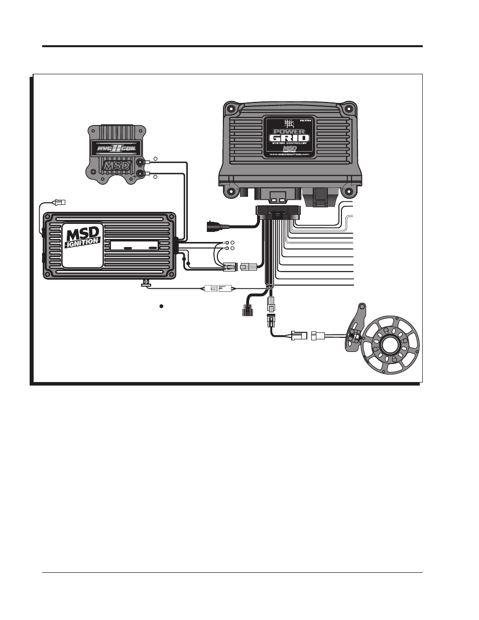
Figure 6 Wiring the Power Grid Controller to MSD 6AL.
ALERTS:
There are a variety of alerts that can arise in the Power Grid System Controller. If there are any errors or
other causes of alert, the LED on the front of the controller will show red. Any time the red light shows the
alerts should be checked so that errors can be corrected. By default, a pop-up box will appear as soon
as an alert is registered. The pop-up window has a check box to disable the pop-ups if desired.
The alerts window can also be opened manually two ways. On the bottom bar of the program window
pane there is an alert counter that will show the number of alerts present. A single click on the alert counter
at any time will open the alert window. The alert window can also be opened by going to the View menu
on the task bar.