10 installation instructions m s d – MSD 7730 Power Grid System - Controller Only Installation User Manual
Page 10
10
INSTALLATION INSTRUCTIONS
M S D
• W W W . M S D P E R F O R M A N C E . C O M • ( 9 1 5 ) 8 5 7 - 5 2 0 0 • F A X ( 9 1 5 ) 8 5 7 - 3 3 4 4
space on the on the Racepak system. To be compatible the user must have a Racepak Data VNet Logger
using DatLink Software v3.7.4 or higher. Default settings will send 13 channels of data to the RacePak system.
Settings:
This tab has two possible adjustments. The first setting allows a user to turn the data recording off,
if desired. The second control tells the system what to do if the SD card is full. This setting allows
the system to either stop recording or begin to write over data with the lowest recording name. By
default the system is on and will overwrite once the memory is full.
Channels:
Each available data trace within the 7730 is listed in this tab. Each trace can be disabled individually
in order to remove unneeded traces and generate smaller files. The Ignition In channel and the
Ignition Out channel are high resolution and they generate the most amount of data at high engine
rpm.
Start Recording:
The settings here tell the controller when to start recording data so that only useful information is
stored. The recorder can be started by RPM alone or by adding a function to the RPM. For example,
the default setting starts recording as soon as the Launch Rev wire is activated and the RPM is
above 3,000.
Stop Recording:
In this tab the user controls when to stop recording. The recording can be stopped by reaching a
lower rpm limit or a trigger such as a step wire signal. When stopping recording only one of these
setting values must be triggered. There is also a setting to keep recording for some time after the
trigger to ensure that all useful data is captured. Finally, there is a user set maximum recording time
limit to ensure recording stops even if the system is not triggered for any reason.
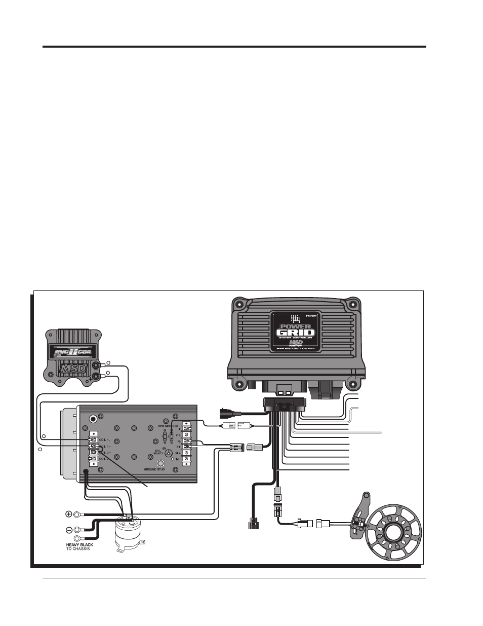
Figure 4 Wiring the Power Grid Controller to MSD 8-Plus.
MSD
CAN
LEGACY IGNITION
SWITCHED IGNITION 12V
GREEN - STEP 5
LT. GREEN - STEP 4
TAN - STEP 3
VIOLET - STEP 2
PINK - STEP 1
BLUE - LAUNCH
LT. BLUE - BURN OUT
BRN/WHITE - RPM/TIME SWITCH
WHITE - POINTS IN
GRAY - TACH
YELLOW - SHIFT LIGHT
GREEN
GREEN
VIOLET
VIOLET
SUPPLIED JUMPER
ORANGE
BLACK
RED
WHITE
ORANGE
BLACK
+
-
ORANGE
BLACK
+
-
BATTERY
BATTERY
V-NET
CABLE