Installation, Relay connections, Connecting the output relays – ACU-RITE DRO 200E User Manual
Page 30
INSTALLATION
DRO 200E
26
The readout has three output relays:
•
The Retract relay indicates to the control that the ram has reached the target
depth. The operator can define how far the ram will retract from the target
depth. The ram can be raised to a pre-determined position or a preset distance
from the target depth. The characteristics of your particular control and work
piece setup will determine how the operator should set the Retract relay.
•
The Dwell relay tells the control to hold at the target depth (the bottom or top of
the burn) in order to obtain a better finish or to allow an orbiter to operate. The
operator can set this dwell to a specified time period, or with the optional Spark
Detector, it can be set for a sparkout condition.
•
The Position Hold relay is active only while the Dwell relay is de-energized. It
maintains the relative position of the ram with respect to the target depth. If
the ram position is above the target depth, the relay is de-energized (contacts
open). If the ram position moves below target depth, the relay is energized (con-
tacts closed). Refer to the Relay Timing Diagrams on pgs. 27-29.
The optional Spark Detector can be connected so that the readout can determine the
sparkout condition. Sparkout occurs when no spark is detected for a predetermined
period of time. The Spark Detector connects to the Electronic Edge Finder input on
the back of the readout.
Relay Connections
The Retract and Dwell relay contact are rated at 1 amp at 30 VDC, 0.5 amp at 125
VAC. The Position Hold relay contact rating is 0.10 amp at 30 VDC, 0.10 amp at
125 VAC.
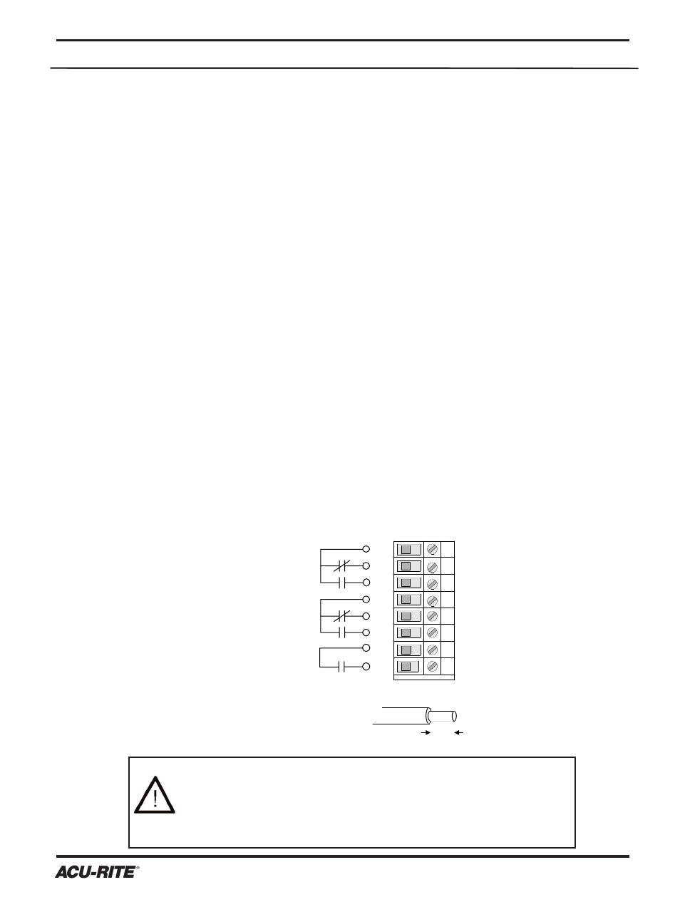
Connecting the Output Relays
2
1
3
4
5
6
Retract
Relay
Dwell
Relay
.35"
9 mm
14 - 22 AWG
wire, solid or stranded
insulation rating: 600V/80
o
C min.
8
7
Position
Hold
Relay
CAUTION
Connecting the relays improperly or exceeding the specified
limits may result in damage to the readout system or to exter-
nal equipment. Equipment connecting to the CFI relays is to
have no live parts that are accessible.