Raising/lowering elevating legrest assembly, Ƽ warning – Activeforever Invacare Tracer IV Wheelchair User Manual
Page 28
SECTION 4—FRONT RIGGINGS
Tracer
®
IV
28
Part No. 1110558
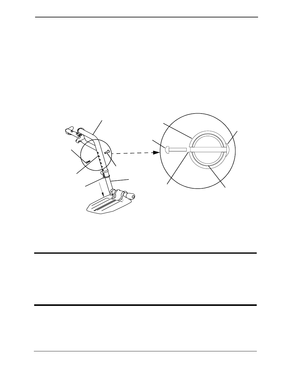
5. Adjust the footplate assembly height by aligning the desired adjustment holes in the
upper front rigging support and lower footplate assembly.
6. From the outside of the swingaway front rigging, insert the threaded rivet through
both the front rigging support and the footplate assembly.
7. From the inside of the swingaway front rigging, insert the button head screw through
the appropriate adjustment hole and thread into the threaded rivet.
8. Using a screwdriver to hold the threaded rivet in position, securely tighten the button
head screw. Torque to 32 in-lbs.
9. Rotate cam lock lever down to locked position.
10. Repeat STEPS 1-9 to adjust the remaining footrest.
FIGURE 4.3 Bolt-In-Place Height
Raising/Lowering Elevating Legrest Assembly
ƽ WARNING
Ensure hands and fingers are clear of elevating legrest mechanism before pushing
release lever to lower the elevating legrest. Otherwise injury may occur due to
pinch points.
The wheelchair user’s leg MUST be supported by an assistant before attempting to
lower legrest.
NOTE: For this procedure, refer to FIGURE 4.4 on page 29.
Front Rigging
Support
Button Head
Screw
Threaded Rivet
Footplate
Assembly
NOTE: Swingaway footrest shown.
Footplate
Assembly
Threaded
Rivet
Front Rigging
Support
Button Head
Screw
Adjustment
Hole
Inside of
Swingaway
Front Rigging
Adjustment
Hole
Cam Lock
Lever
Outside of
Swingaway
Front Rigging