Jp1a, Com1: (type db9) – Acnodes PC 8719 User Manual
Page 19
19. BT1:
POWER on/off Button, They are used to connect power switch button. The two pins are
disconnected under normal condition. You may short them temporarily to realize system
startup & shutdown or awaken the system from sleep state.
20. JP1:
(2.0mm Pitch 2x3 Pin Header),COM1 jumper setting, pin 1~6 are used to select signal out of pin 9
of COM1 port.
JP1 Pin#
Function
Close 1-2
COM1 RI (Ring Indicator) (default)
Close 3-4
COM1 Pin9=+5V
(option)
Close 5-6
COM1 Pin9=+12V
(option)
21. JP1A:
(2.0mm Pitch 2x10 Pin Header),COM1 jumper setting, it provides selectable RS232 or
RS422 or RS485 serial signal output.
Function
JP1A Pin#
RS232
(Default)
Close:
Pin1-3, Pin2-4, Pin7-9, Pin8-10, Pin13-14
RS422
(option)
Close:
Pin3-5, Pin6-8, Pin9-11, Pin10-12, Pin17-18
RS485
(option)
Close:
Pin3-5, Pin6-8, Pin9-11, Pin10-12, Pin15-16
Pin19-20
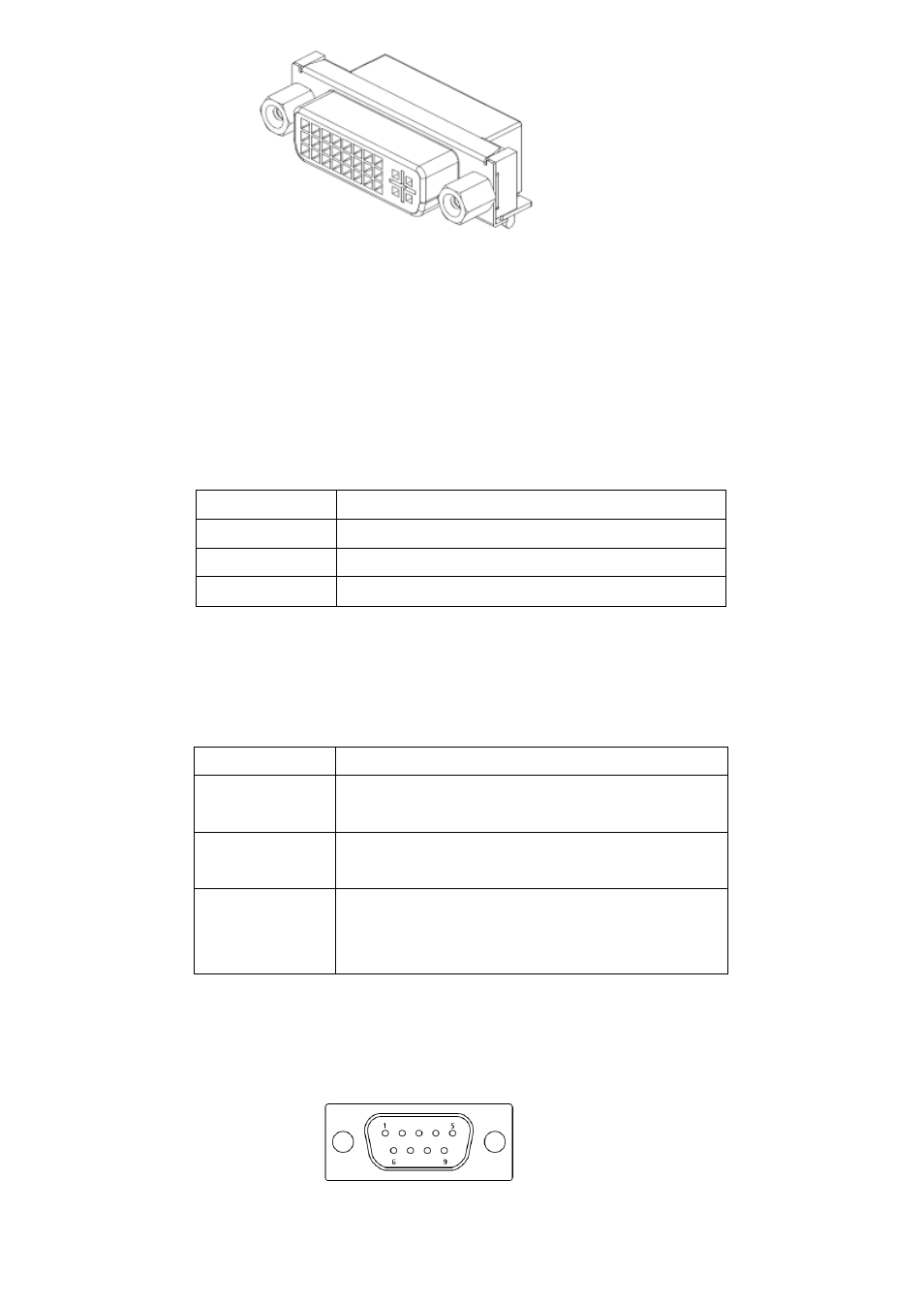
22. COM1:
(Type DB9),
Rear serial port, standard DB9 Male serial port is provided to make a direct
connection to serial devices.