Device initialization, Bus width detection – Xilinx LogiCore PCI v3.0 User Manual
Page 29
PCI v3.0.151 Getting Started Guide
29
UG157 August 31, 2005
Device Initialization
R
Device Initialization
Immediately after FPGA configuration, both the PCI interface and the user application are
initialized by the startup mechanism present in all Virtex and Spartan devices.
During normal operation, the assertion of RST# on the PCI bus reinitializes the PCI
interface and three-states all PCI bus signals. This behavior is fully compliant with the PCI
Local Bus Specification. The PCI interface is designed to correctly handle asynchronous
resets.
Typically, the user application must be initialized each time the PCI interface is initialized.
In this case, use the RST output of the PCI interface as the asynchronous reset signal for the
user application. If part of the user application requires an initialization capability that is
asynchronous to PCI bus resets, simply design the user application with a separate reset
signal.
Note that these reset schemes require the use of routing resources to distribute reset
signals, because the global resource is not used. The use of the global reset resource is not
recommended.
Bus Width Detection
A PCI interface that provides a 64-bit datapath needs to know if it is connected to a 64-bit
bus or a 32-bit bus. The SLOT64 signal is an input to the PCI64 interface for this purpose.
The PCI bus specification provides a mechanism for PCI agents to determine the width of
the bus by sampling the state of the REQ64# signal at the rising edge of RST#.
In embedded systems, where the bus width is known by design, the user application can
simply drive SLOT64 with the appropriate value. Note that SLOT64 must never be driven
with a static value; it should always be driven from the output of a flip-flop.
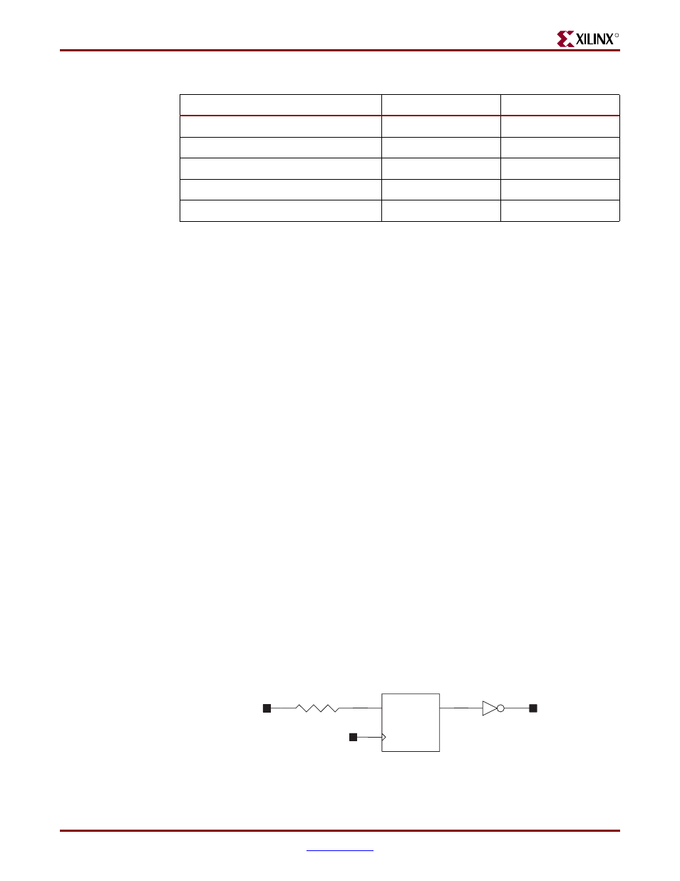
In designs for open systems, the bus width is not known in advance. In this case, include a
separate latch or flip-flop, external to the FPGA, to sample REQ64#.
shows how
this can be accomplished.
2vp40ff1152_64_66.ncd
153
246
2vp50ff1152_64_66.ncd
153
246
v200fg256_32_66.ncd
90
86
v200efg256_32_66.ncd
90
86
v400fg676_32_66.ncd
90
86
Table 3-2:
Guide File Information
Guide File
Components
Connections
Figure 3-1:
Sample SLOT64 Generation
Q
D
C
SLOT64
REQ64#
RST#
RESISTOR