Zebra Technologies P520 User Manual
Page 58
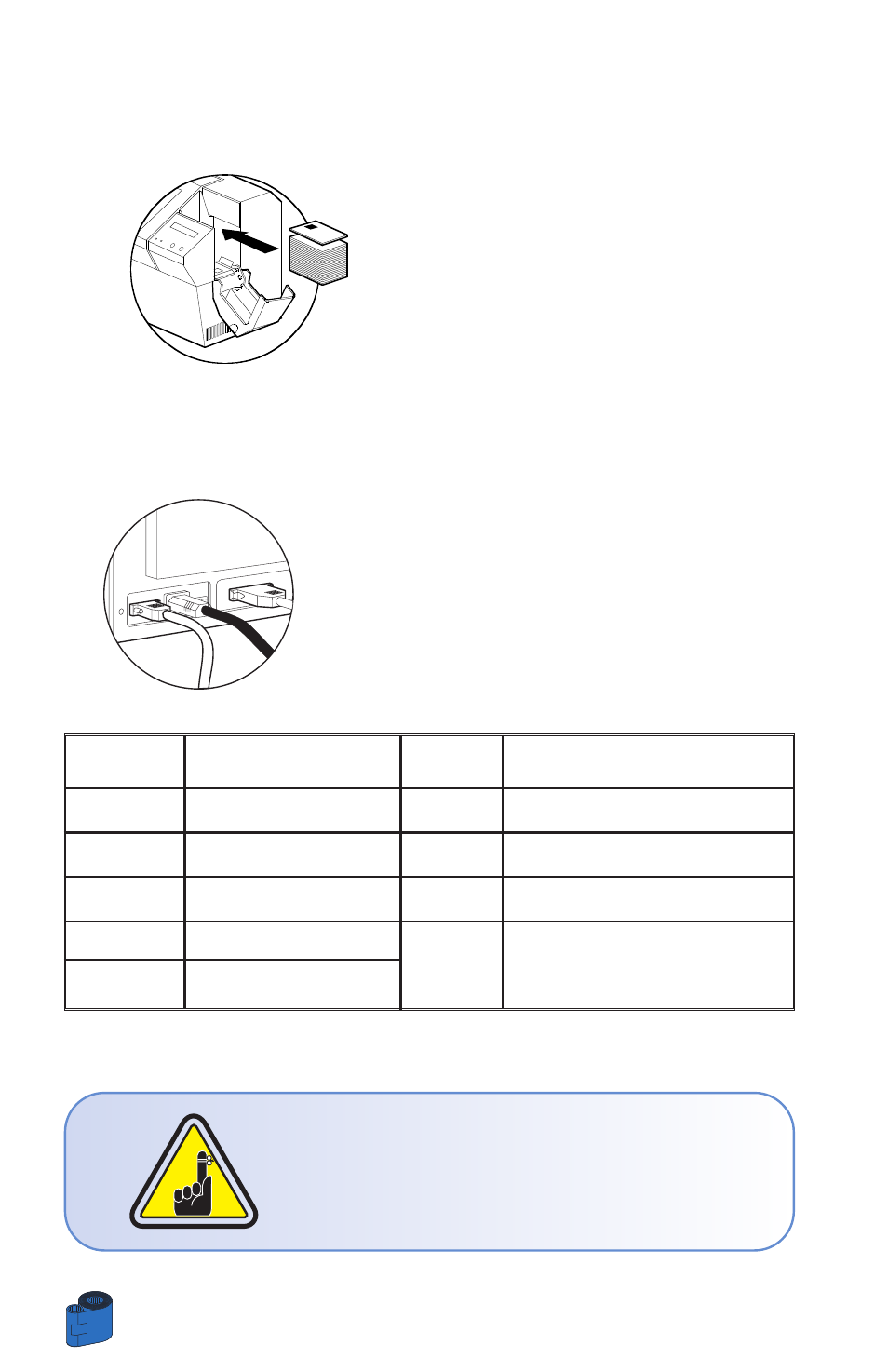
A •
MEDIA LOADING ORIENTATION
Position the cards with the Smart Card Chip at the
top of the card and towards the printer.
B •
SMART CARD CONTACT STATION INTERFACE
When a command to the parallel printer interface
sends a card to the Smart Card Contact Station, the
printer connects the Smart Card Contact Station to
the female DB-9 connector on the rear of the printer.
An attached external Smart Card Programmer can
be used to program Smart card chips
Refer to the Card printer programmer’s Manual for complete programming information.
DO NOT position printing over the Smart Card Chip.
APPENDIX B
48
DB - 9
SMART CARD
DB - 9
SMART CARD
PINS
CONTACT POINTS
PINS
CONTACT POINTS
1
CI (VCC)
6
C6 (Vpp)
2
C2 (Reset)
7
C7 (I/O)
3
C3 (Clock)
8
C8 (RFU)
4
C4 (RFU)
5
C5 (GND)
9
(GND when chip is at station)
- TLP 2824 (60 pages)
- 400 (78 pages)
- 2824 (21 pages)
- S600 (94 pages)
- Printers (69 pages)
- 2844 Printer (47 pages)
- P310i (43 pages)
- 3742 (30 pages)
- R-140 (126 pages)
- ZEBRA Z4M H-974 (57 pages)
- P520i (2 pages)
- Mobile Printer (40 pages)
- R110XiTM (184 pages)
- XiIII Series (116 pages)
- PrintServer (157 pages)
- Z4000 (98 pages)
- Z SERIES 79695L-002 (156 pages)
- ZEBRA P205 (42 pages)
- 105Se (106 pages)
- 2722 (30 pages)
- Zebra S Series 105SL (130 pages)
- XiIIIPlus (40 pages)
- Zebra LP 2824-Z (62 pages)
- ZEBRA XI4TM (190 pages)
- P310C (46 pages)
- R170XI (184 pages)
- R402 (72 pages)
- SL5000r/T5000r (50 pages)
- T402 (62 pages)
- TTP 7030 (128 pages)
- Zebra P330i (66 pages)
- Zebra Z6000 (98 pages)
- XiII-Series (118 pages)
- P1013372-001 REV. A (216 pages)
- ZebraNet ZM600TM (130 pages)
- RW SERIES (84 pages)
- LP 2824 (56 pages)
- TTP 8000 (132 pages)
- ZEBRA QL UMAN-QLP-001 (86 pages)
- LP 2844 (54 pages)
- LP2443 (24 pages)
- RXI SERIES (UHF) (19 pages)
- Zebra P120i (78 pages)
- DA402 (56 pages)
- P320i (49 pages)