Rear panel, 2 rear, Panel -2 – ZyXEL Communications EES-1024AF User Manual
Page 30: Figure 2-2 the led -2, Table 2-1 the led descriptions -2, 2 rear panel, Console port, Led indicators
EES-1024AF Intelligent Ethernet Switch
2-2
Hardware Connections
Console Port
Console management can be done through the Console Port. It requires a direct connection between the switch and
a computer via a RS-232 cable.
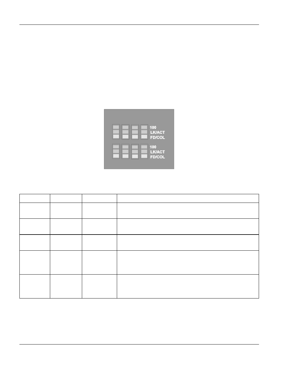
LED Indicators
All LED indicators are located on the front panel of the switch. They provide a real-time indication of system and
operational status. The following table gives descriptions of the LED status and their meanings.
Figure 2-2 The LED
Table 2-1 The LED Descriptions
LED COLOR STATUS
DESCRIPTION
ON
The system is turned on.
PWR Green
OFF
The system is off.
ON
The system is functioning abnormally.
ALM Red
OFF
The system is functioning normally.
ON
The link to a 100 Mbps Ethernet network is up.
100 Green
OFF
No device attached or in 10Mbps mode.
ON
The port is connected with a device.
Blinking
The port is receiving or transmitting data.
LK/ACT Green
Off
No device attached.
ON
The port is operating in Full-duplex mode.
Blinking Packet
collision occurred.
FD/COL Yellow
OFF
No device attached or in half-duplex mode.
2.1.2 Rear
Panel
The 3-pronged power plug and the On/off switch are located at the back of the switch. The ventilation fan is located
on the side of the switch. The switch works with AC in the range 100-240V AC, 50-60Hz.