Boiler-side piping, Manual – Weil-McLain PLUS LINE PLUS-E017-A/1206 User Manual
Page 39
Part Number PLUS-E017-A/1206
9
Manual
• Installation • Start-Up • Usage • Maintenance • Parts
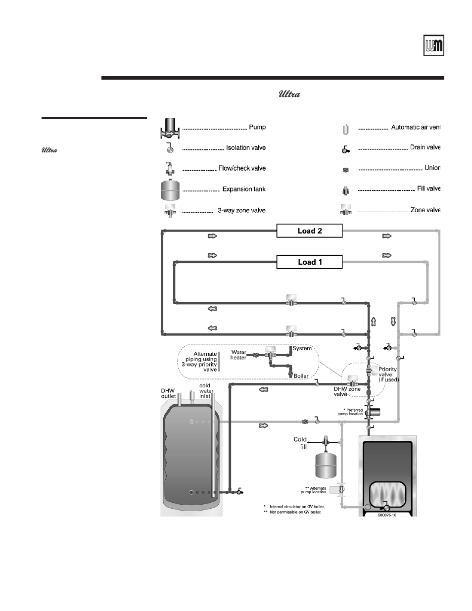
1. This drawing is conceptual only. It shows representative piping components and layout.
Weil-McLain does not represent that this drawing meets any particular mechanical or
building codes. The installer is responsible for inclusion of all required safety devices, or
other miscellaneous piping hardware not shown on drawing. The installer is responsible
for proper sizing/selection of all hardware shown on this diagram.
2. See Weil-McLain installation instructions for specific details on installing the boiler.
Notes
Figure 23
GOLD Plus 30/40/60/80
Plus 40/60/80
PLUS 100/110/119
• Zoning
with zone valves
• Place
pumps at beginnings of
zones. Placing them at the ends
of zones could result in heating
idle zones.
• Size
manifold piping for total flow
of all zone pumps.
Wiring options:
• Figure
34, page 52 — WMZV
zone valve controller, priority
optional (priority valve not
required)
• Figure
40, page 58 or
Figure 41, page 59 — Priority
using 2-way valve
• Figure
37, page 55 or Figure
38, page 56 — Priority with
2-way priority valve and 2-way
zone valve on water heater
circuit
• Figure
35, page 53 or
Figure 36, page 54 — No
priority, using 2-way zone valve
on water heater circuit
C
Boiler-side piping
(except
Gas)
continued