Install system water piping, Plus line, Indirect-fired water heaters – series 3 – Weil-McLain PLUS LINE PLUS-E017-A/1206 User Manual
Page 26: Zoning with zone valves
2
Part Number PLUS-E017-A/1206
PLUS LINE
Indirect-Fired Water Heaters – Series 3
Install system water piping
(space heating)
(continued)
Figure 12
Zone valve zoning plus optional water
heater piping
Zoning with zone valves
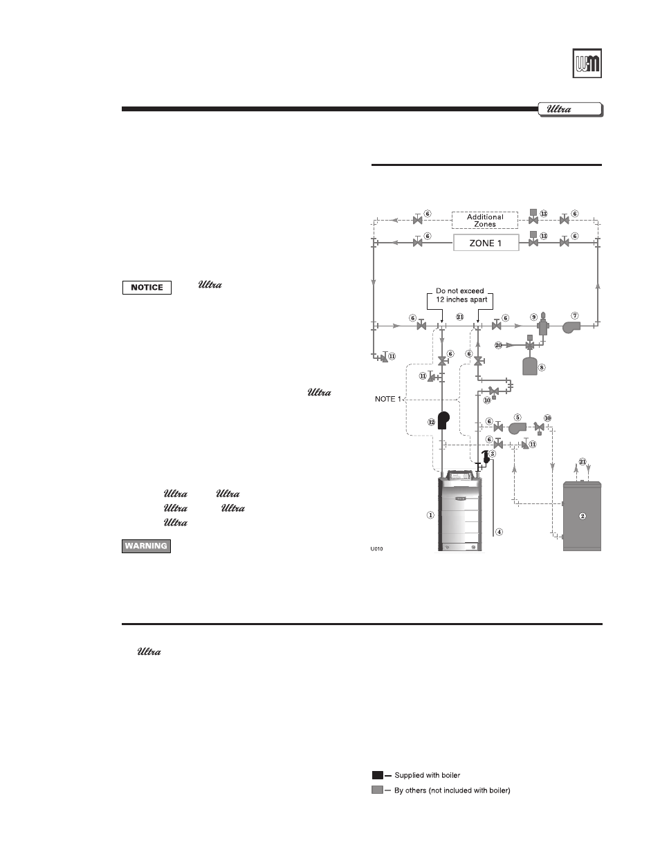
1. Connect boiler to system as shown in Figure 12
when zone valve zoning. The primary/secondary
piping shown ensures the boiler loop will have suf-
ficient flow. It also avoids applying the high head
of the boiler circulator to the zone valves.
2. Connect water heater (domestic hot water) pip-
ing to indirect storage water heater as shown in
Section A of this manual.
The
PhD Control Module turns off
space heating during water heater heat-
ing. The boiler circulator will turn off,
preventing hot water from circulating to
the system. The flow/check valve shown
on the boiler outlet piping prevents grav-
ity circulation in the boiler loop during
water heater heating.
. Controlling the system circulator
a. To cycle the system circulator from the
PhD
control module, add a circulator relay wired to the
boiler circulator terminals as shown on page 0.
Legend
Figure
12
1
boiler
2 PLUS-Line indirect water heater
3 Boiler relief valve (see boiler manual for piping details)
4 Boiler relief valve discharge piping (see boiler manual for
details)
5 Water heater circulator (see page 7 for suggested
sizing)
6 Isolation valves
7 System circulator
8 Diaphragm (or bladder) type expansion tank (see page 3
for piping of closed-type expansion tank, if used)
9 Air separator [with automatic air vent only on systems
using diaphragm (or bladder) type expansion tank]
10 Flow/check valves (with weighted seats to prevent gravity
circulation)
11 Purge/drain valves
12 Boiler circulator
13 Zone valves, typical
20 Make-up water supply
21 Primary/secondary connection
NOTE 1:
To ensure adequate flow rate through the
boiler, use the following pipe size on all
boiler loop piping (connecting boiler to and
from the primary/secondary connection,
item 21):
-80 or
-10 – 1” or larger.
-1 or
-20 – 1¼” or larger.
-10 – 1½” or larger.
Use at least the minimum piping size
above and pipe the boiler using only pri-
mary/secondary piping as shown. Failure
to follow these guidelines could result in
system problems.
B1
Gas