Wegener Communications UNITY 4600 User Manual
Page 24
U
NITY
4600 U
SER
’
S
M
ANUAL
800032-01 Rev. F
16
www.wegener.com
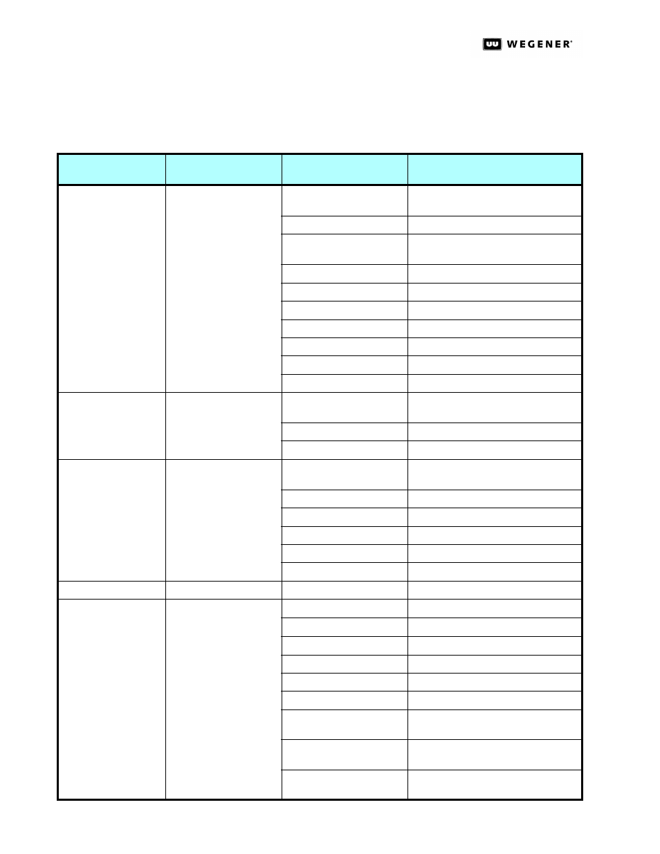
Table 2.4: Rear Panel Connectors below lists the U4600 connectors on the rear panel,
their types and pinout information. See
Interpreting LEDs on page 43 for descriptions of
rear-panel indicators.
Table 2.4: Rear Panel Connectors
Connector
Designation
Type
Pin
Signal Name
Alarm Cuing
10-pin male header
(mates to removable
terminal-strip)
1 (on left as viewed from
rear of unit)
OK (COM closes here when OK)
2
COM:
3
Alarm (COM closes here on alarm or if
power is off)
4
GND
5
Cue Relay #1: N.C. contact
6
Cue Relay #1: Common contact
7
Cue Relay #1: N.O. contact
8
Cue Relay #2: N.C. contact
9
Cue Relay #2: Common contact
10
Cue Relay #2: N.O. contact
DTMF
3-pin male header (mates
to removable terminal-
strip)
1 (on left as viewed from
rear of unit)
DTMF tone, non-inverted output
2
GND
3
DTMF tone, inverted output
Audio (same for both
ports 1 and 2)
6-pin male header (mates
to removable term strip)
1 (on left as viewed from
rear of unit)
Right ‘+’
2
Right GND
3
Right ‘-’
4
Left ‘+’
5
Left GND
6
Left ‘-’
Composite Video Out BNC Jack
Composite Video Out
Serial Control
RS232, 9-pin D female
jacks
1
DCD (internally pulled to +5V)
2
RxD (data output)
3
TxD (data input)
4
DTR (not connected)
5
GND
6
DSR (internally pulled to +5V)
7
RTS (internally pulled to +5V, may be
upgraded for handshaking)
8
CTS (not used presently, may be
upgraded for handshaking)
9
RI (internally pulled to +5V, with weak
current limiting)