Spring and screw terminal modules – VXI VT1422A User Manual
Page 66
64 Programming the VT1422A & VT1529A/B for Remote Strain Measurement
Spring and Screw
Terminal Modules
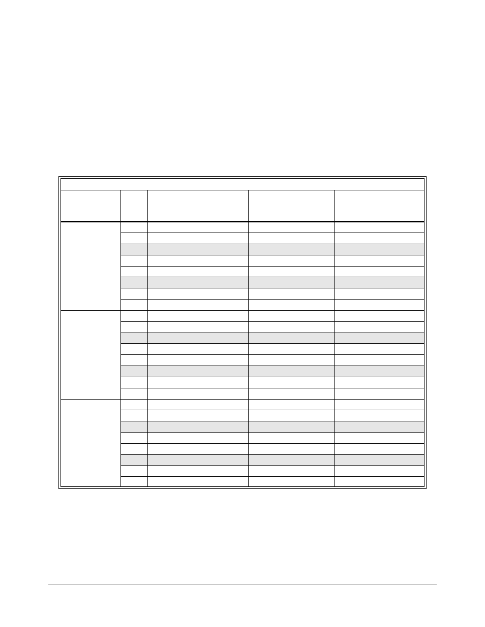
For mixed on-board SCP channels and RSCU operation, spring or screw
type terminal modules can be used. For standard SCP channel connections,
see Chapter 2 “Field Wiring” on page 35. For remote channels, connect the
individual wires from each VT1529A/B’s data interface cable to the
appropriate terminals for remote channel operation. The VT1539A SCP is
supplied with signal locator labels for each SCP position on a Spring
Terminal Module. No label is provided for the Screw terminal module.
Instead, Table 3-3 provides the relationship between each VT1539A signal
name and associated terminal name as printed on the Terminal Module.
Note: In the table below, color combinations may vary.
Table 3-3. VT1539A Signal Names
SCP Signal Names - to - Terminal Names
SCP Position
Plug
Pin#
VT1539A Signal Name
(with EIA/TIA-568A
wire color-code)
Terminal Name on
Terminal Module
(SCP’s low channel)
Terminal Name on
Terminal Module
(SCP’s High Channel)
SCP Position 0
Addresses
10000 to 10131
1
Analog+ (wht-green)
HI 00
HI 01
2
Analog- (green)
LO 00
LO 01
3
Cal+ (wht-orange)
HI 02
HI 03
4
RS-485+ (blue)
HI 04
HI 05
5
RS-485- (wht-blue)
LO 04
LO 05
6
Cal- (orange)
LO 02
LO 03
7
Trigger+ (wht-brown)
HI 06
HI 07
8
Trigger- (brown)
LO 06
LO 07
SCP Position 1
Addresses
10800 to 10931
1
Analog+ (wht-green)
HI 08
HI 09
2
Analog- (green)
LO 08
LO 09
3
Cal+ (wht-orange)
HI 10
HI 11
4
RS-485+ (blue)
HI 12
HI 13
5
RS-485- (wht-blue)
LO 12
LO 13
6
Cal- (orange)
LO 10
LO 11
7
Trigger+ (wht-brown)
HI 14
HI 15
8
Trigger- (brown)
LO 14
LO 16
SCP Position 2
Addresses
11600 to 11731
1
Analog+ (wht-green)
HI 16
HI 17
2
Analog- (green)
LO 16
LO 17
3
Cal+ (wht-orange)
HI 18
HI 19
4
RS-485+ (blue)
HI 20
HI 21
5
RS-485- (wht-blue)
LO 20
LO 21
6
Cal- (orange)
LO 18
LO 19
7
Trigger+ (wht-brown)
HI 22
HI 23
8
Trigger- (brown)
LO 22
LO 23