Linking resistance measurements – VXI VT1422A User Manual
Page 113
Programming the VT1422A for Data Acquisition and Control 111
Linking Resistance
Measurements
To link channels to the resistance EU conversion send the
[SENSe:]FUNCtion:RESistance
<excite_current>,[<range>,](@<ch_list>) command.
Resistance measurements assume that there is at least one Current Source
SCP installed (eight current sources per SCP). See Figure 4-5.
•
The
what the Current Source SCP channel is now set to.
is specified in amps dc and the choices for the VT1505A SCP are
30e-6 (or MIN) and 488e-6 (or MAX). Select 488 µA for measuring
resistances of less than 8,000
Ω. Select 30 µA for resistances of
8,000
Ω and above.
•
The optional
range. When not specified (defaulted), the module uses auto-range.
•
The
resistance EU conversion. These channels will sense the voltage across
the unknown resistance. Each can be a Current Source SCP channel
(a two-wire resistance measurement) or a sense channel separate from
the Current Source SCP channel (a four-wire resistance measurement).
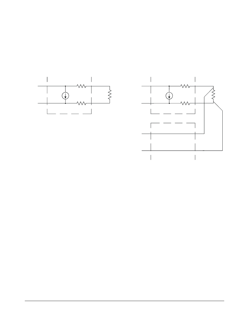
See Figure 4-5 for diagrams of these measurement connections.
* Because of the 150 ohm resistor in series with each of the
current source outputs, Two-Wire resistance and temperature
measurements will have a 300 ohm offset.
** The current source Hi terminal is the negative voltage node.
The current source LO terminal is the positive voltage node.
Two-Wire Measurement
(not recommended **)
Current Source SCP
Field Wiring
Sens
e
C
h
annel
*150 ohm 5%
*150 ohm 5%
R
Four-Wire Measurement
Current Source SCP
Field Wiring
HI
LO
HI
LO
R
Any Sense SCP
Sens
e
C
h
annel
HI
LO
Figure 4-5. Resistance Measurement Sensing