Screw terminal module layout, H 2-6, Rt 1 – VXI VT1422A User Manual
Page 43
Field Wiring 43
Screw Terminal
Module Layout
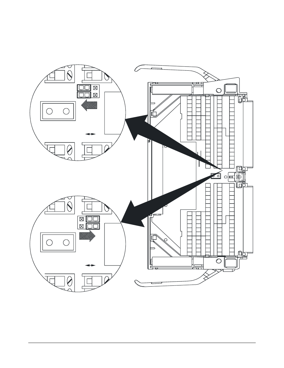
Figure 2-6 shows the VT1422A Option 011 Screw Terminal Module
features and jumper locations.
Jumper Detail
On-Board Reference
Temperature Sensing
JM1
RE
M
ON BOARD
RT
1
JM1
REM
O
N
BOARD
RT
1
Remote Reference
Temperature Sensing
Figure 2-6. VT1422A Screw Terminal Module
This manual is related to the following products: