Adjustment mode setting, P. 31, P. 31) – TOA Electronics M-9000 User Manual
Page 31
31
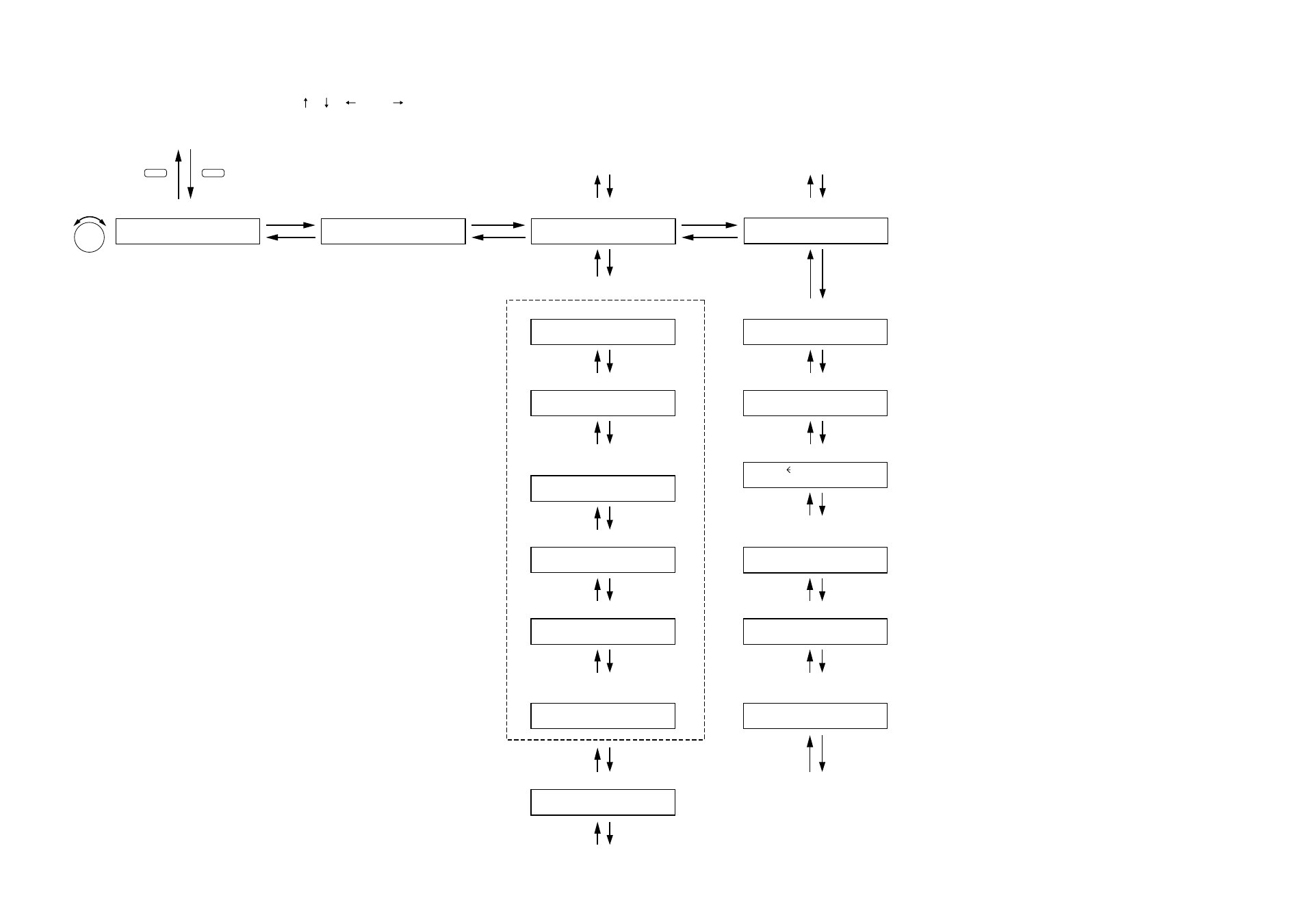
11.3.5. Adjustment mode setting
The screen display examples shown below may differ from actual displays.
The on-screen indications shown in red here (actually shown by flashing cursors) are parameters or setting contents to be selected with the Parameter setting knob, input channel selection key or other designated keys.
Unless otherwise specified, the indications of the [ ], [ ], [
], and [
] arrows represent that the screen is switched with the Screen shift key.
A D J U S T
E V E N T 0 1 – R O U T E
O N
PARAMETER
Ducker attenuation level setting
Input ON/OFF and Input gain settings
D U C K E R
D E P T H
– 2 0
Ducker attenuation level setting
(For the channel on which the D-001T is used)
L O U D N E S S –
O N
C O M P R E S S O R –
O F F
V O X S E N S I T I V I T Y
– 3 0
VOX (Voice-Operating Switch) setting
H P F –
4 0 0
H Z
L P F –
1 2 5
.
Compressor setting
Output ON/OFF and Output gain settings
O U T 1 – O U T 1
O N
0 0
Output ON/OFF and Output gain settings
B A S S
+ 1 2
T R E B L E
– 1 0
L O U D N E S S –
O N
C O M P R E S S O R –
O F F
H P F –
4 0 0
H Z
L P F –
1 2 5
.
S P
E Q
A L L
F L A T
EQ ON/OFF, Band number, Gain, Q,
and Center frequency settings
E Q
1 0
+ 1 2
0 7
3 1 5
.
I N 1 – I N 1
O N
0 0
Input ON/OFF and Input gain settings
.
.
:
:
UTILITY
MEMORY
Normal operation mode
Setting menu screen
Press for over 2 seconds.
B A S S
+ 1 2
T R E B L E
– 1 0
EQ ON/OFF, Band number, Gain, Q,
and Center frequency settings
E Q
1 0
+ 1 2
0 7
3 1 5
.
Note
Press the Enter key to
confirm this setting.