Utility setting, Set the utility function. (refer to, P. 29 – TOA Electronics M-9000 User Manual
Page 29: P. 29)
29
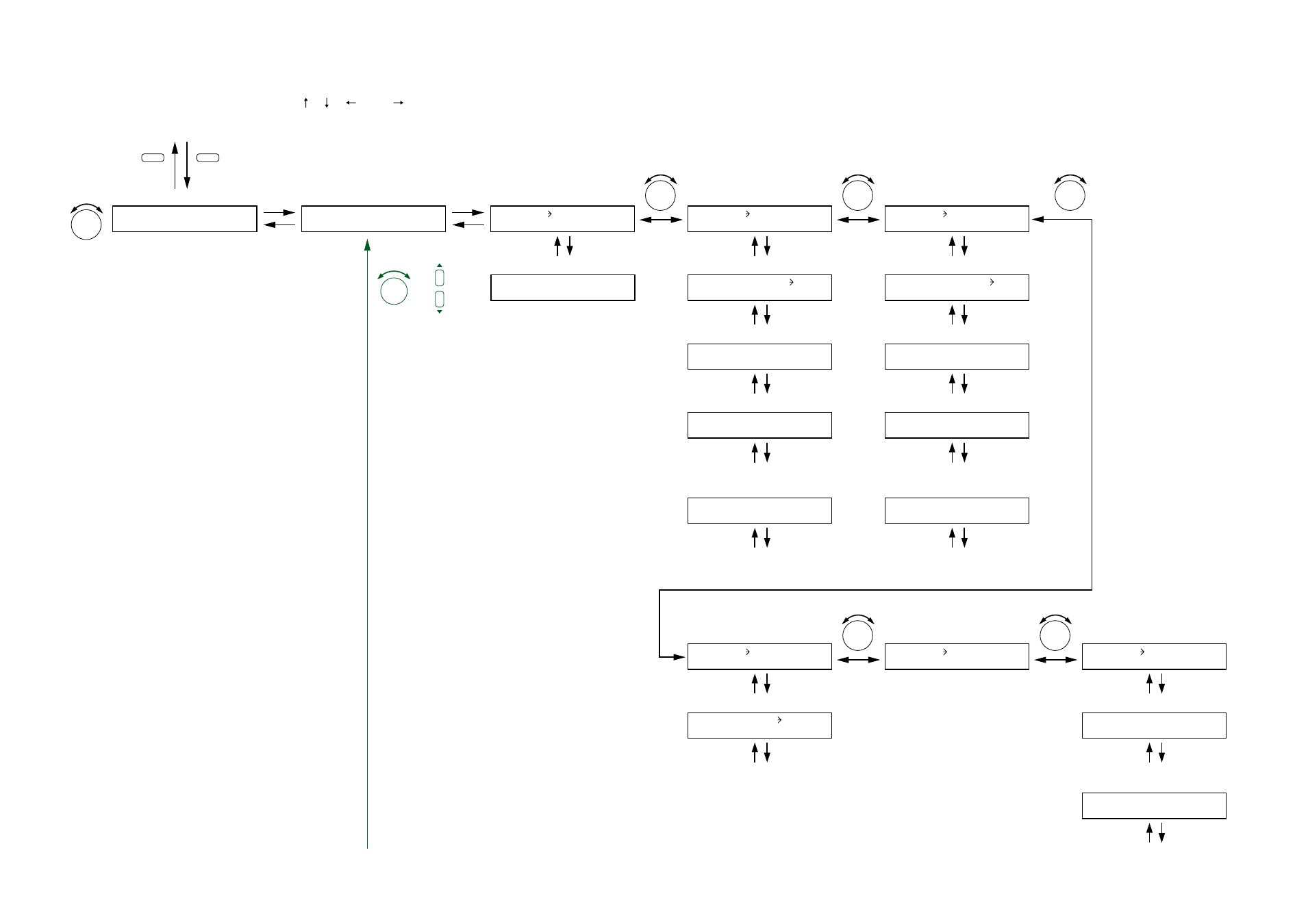
11.3.4. Utility setting
The screen display examples shown below may differ from actual displays.
The on-screen indications shown in red here (actually shown by flashing cursors) are parameters or setting contents to be selected with the Parameter setting knob, input channel selection key or other designated keys.
Unless otherwise specified, the indications of the [ ], [ ], [
], and [
] arrows represent that the screen is switched with the Screen shift key.
U T I L I T Y – S E T T I N G
U T I L I T Y
C - I N
Function selection
(when the control input is selected)
PARAMETER
Control input number selection,
Control input function setting
Control input number selection,
Control input function setting
Control input number selection,
Control input function setting
Control input number selection,
Control input function setting
C - I N 0 1
E V E N T
N O N E
Event assignment display
(When the control input function
is set to VOLUP)
Volume increasing level setting
Interlock output control setting
Interlock output terminal setting
(When the interlockl output contro is ON)
(When the control input function
is set to VOLDWN)
PARAMETER
To the next page
Volume decreasing level setting
Interlock output control setting
Interlock output terminal setting
(When the interlock output control is ON)
(When the control input function
is set to MUTE)
(When the control input function
is set to POWER)
Control input number selection,
Control input function setting
(When the control input function
is set to EMG-MUTE)
Interlock output control setting
C - I N 0 1 –
C O U T 0 1
Interlock output terminal setting
(When the interlock control output is ON)
C - I N
0 1
–
N O N E
C - I N
0 1
–
V O L U P
C - I N
0 1
–
M U T E
C - I N 0 1 – V O L U P
0 5
.
C - I N 0 1 – S Y N C
O F F
C - I N 0 1 – S Y N C
O F F
C - I N 0 1 –
C O U T 0 1
C - I N 0 1 –
C O U T 0 1
C - I N 0 1 – V O L U P
I N 1
C - I N
0 1
–
E M G - M U T E
C - I N 0 1 – S Y N C
O N
C - I N
0 1
–
P O W E R
C - I N 0 1 – M U T E
I N 1
C - I N 0 1 – V O L D W N
0 5
.
UTILITY
MEMORY
Normal operation mode
Setting menu screen
Press for over 2 seconds.
PARAMETER
PARAMETER
PARAMETER
PARAMETER
C - I N 0 1 – V O L D W N
I N 1
C - I N
0 1
–
V O L D O W N
Note
All screens that appear when the Setting knob is rotated are
setting screens of the same hierarchy.
The screen to be displayed when the shift key is pressed
differs depending on the set contents.
PARAMETER
or