Appendix 2 interface – Toshiba B-SV4T-GS10-QM User Manual
Page 29
APPENDIX 1 SPECIFICATIONS
ENGLISH VERSION
APPENDIX2 INTERFACE
EA2-1
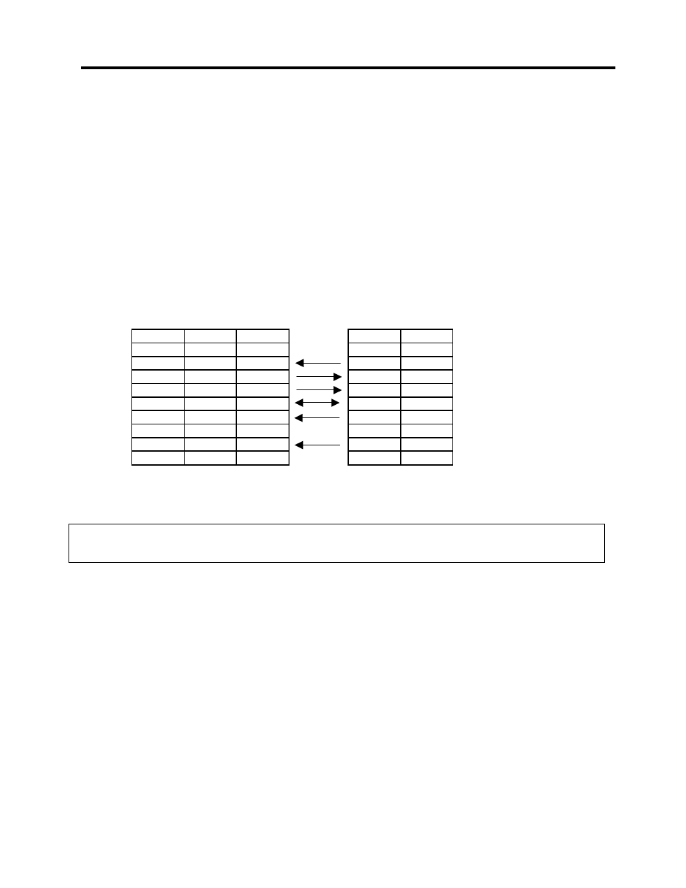
Function
9 pin
25 pin
RXD
2
3
TXD
3
2
DTR
4
20
GND
5
7
DSR
6
6
RTS
7
4
C TS
8
5
APPENDIX 2 INTERFACE
Interface Cables
To prevent radiation and reception of electrical noise, the interface cables must meet the following
requirements:
• Fully shielded and fitted with metal or metallized connector housings.
• Keep as short as possible.
• Should not be bundled tightly with power cords.
• Should not be tied to power line conduits.
RS-232C Cable description
The serial data cable used to connect the printer to a host computer should be one of the following two
types (9-pin or 25-pin connector):
Connector to the Host Computer
Connector to Printer
NOTE:
Use an RS-232C cable with a connector with inch type securing screws.
Pin No. Function
1
+5V
2
TXD
3
RXD
4
RTS
5
GND
6
CTS
7
RTS
8
CTS
9
+5V
- e-STUDIO222cp (16 pages)
- e-STUDIO382p (22 pages)
- Copier (78 pages)
- e-Studio Imaging 5520c (288 pages)
- multifunctional digital color systems e-STUDIO4540C (282 pages)
- B-852 Advance (2 pages)
- GA-1121 (118 pages)
- 720T (8 pages)
- 305 (168 pages)
- TEC EO1-32004 (94 pages)
- TEC DRJST-51 (19 pages)
- MULTIFUNCTIONAL DIGITAL COLOR SYSTEMS 2830C (178 pages)
- B-SP2D (50 pages)
- R-TH10 (86 pages)
- B-682-QP (157 pages)
- B-680-QQ (32 pages)
- e-STUDIO 281C (8 pages)
- TEC EO1-33027E (122 pages)
- MULTIFUNCTIONAL DIGITAL COLOR SYSTEMS e-STUDIO5520C (210 pages)
- 7FM03281000 (34 pages)
- B-570 (90 pages)
- GD-1270 (120 pages)
- ESTUDIO 230L (382 pages)
- 520 (7 pages)
- TEC EM1-33043D (46 pages)
- B-EP2DL (28 pages)
- TRST-A15 SERIES (31 pages)
- TEC B 452 (184 pages)
- TEC EO1-33016E (34 pages)
- B-670-QQ (34 pages)
- REMOTE RECEIPT PRINTER TRST-A00 (35 pages)
- e-STUDIO Printer/Fax/Scanner/Copier (4 pages)
- 282 (48 pages)
- B-480-QP (170 pages)
- B-450-QQ (28 pages)
- B-480-QQ (30 pages)
- B-SA4TP SERIES (114 pages)
- TEC EO1-13016 (24 pages)
- B-450-HS-QQ (34 pages)
- E.STUDIO 603 (216 pages)
- e-STUDIO 170F (244 pages)
- B-SA4 (2 pages)
- TEC EM1-33039E (34 pages)
- B-852 (2 pages)
- B-570 SERIES (158 pages)