Wiring with the wired media card, Wiring with the wired media card -14, Figure 3-7. coupler wiring -14 – Tyco 4100U-S1 User Manual
Page 56: Step 4. wiring network cards
3-14
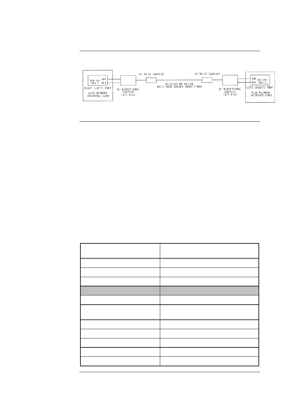
The illustration below shows coupler wiring.
Figure 3-7. Coupler Wiring
Refer to the guidelines and figures in this topic to use wired media cards.
IMPORTANT: TB1 on the wired media card must not be used when it is
connected to the 4100-6014 NIC.
• When the 4100-6056 (565-413) Interface Card is used with the 4100-6014
Network Card, TB1 on the Interface Card cannot be used. Network wiring must
be connected to the motherboard as shown.
• The shield should only be connected at one end of the line. The shield is
connected to the left port.
• Each cable requires two ferrite beads, one at each end. Refer to Figure 5-1 for
bead wiring. Beads can be ordered as 4100-5129 (set of three).
• When wiring leaves the building, 2081-9044 Overvoltage Protectors are
required. One overvoltage protector is installed where wiring leaves the
building; another is installed where wiring enters the next building.
Table 3-5. 566-227 CPU Motherboard Wired Media Connections
CPU Motherboard Port for
Media Card Connected to P5
Wired Media Card Connection
(Left Port)
TB1-4 0
V
TB1-5 Earth
ground
TB1-6 INV
(-)
TB1-7
None
TB1-8 NONINV
(+)
CPU Motherboard Port for
Media Card Connected to P6
Wired Media Card Connection
(Right Port)
TB3-1 NONINV
(+)
TB3-2 Reserved
TB3-3 INV
(-)
TB3-4 Earth
ground
TB3-5 0
V
Continued on next page
Step 4. Wiring Network Cards,
Continued
4190-9010 Coupler
Requirements
(continued)
Wiring with the
Wired Media Card