2 features, 3 system requirements, 1 optional external console – Tripp Lite B020-U08-19-IP User Manual
Page 5: 2 computers, Introduction
5
4.3.6 Operating Systems
Operating System
Versions Supported
Windows
2000 and higher
Linux RedHat
7.1 and higher
Linux SuSE
8.0 and higher
Linux Mandriva (Mandrake)
9.0 and higher
UNIX AIX
4.3 and higher
Operating System
Versions Supported
UNIX Free BSD
4.2 and higher
UNIX Sun
Solaris 8 and higher
Novell Netware
5.0 and higher
Mac
OS 9 and higher
DOS
6.22 and higher
Supported operating systems are shown in the table, below:
4.3 System Requirements
(continued)
4. Introduction
(continued)
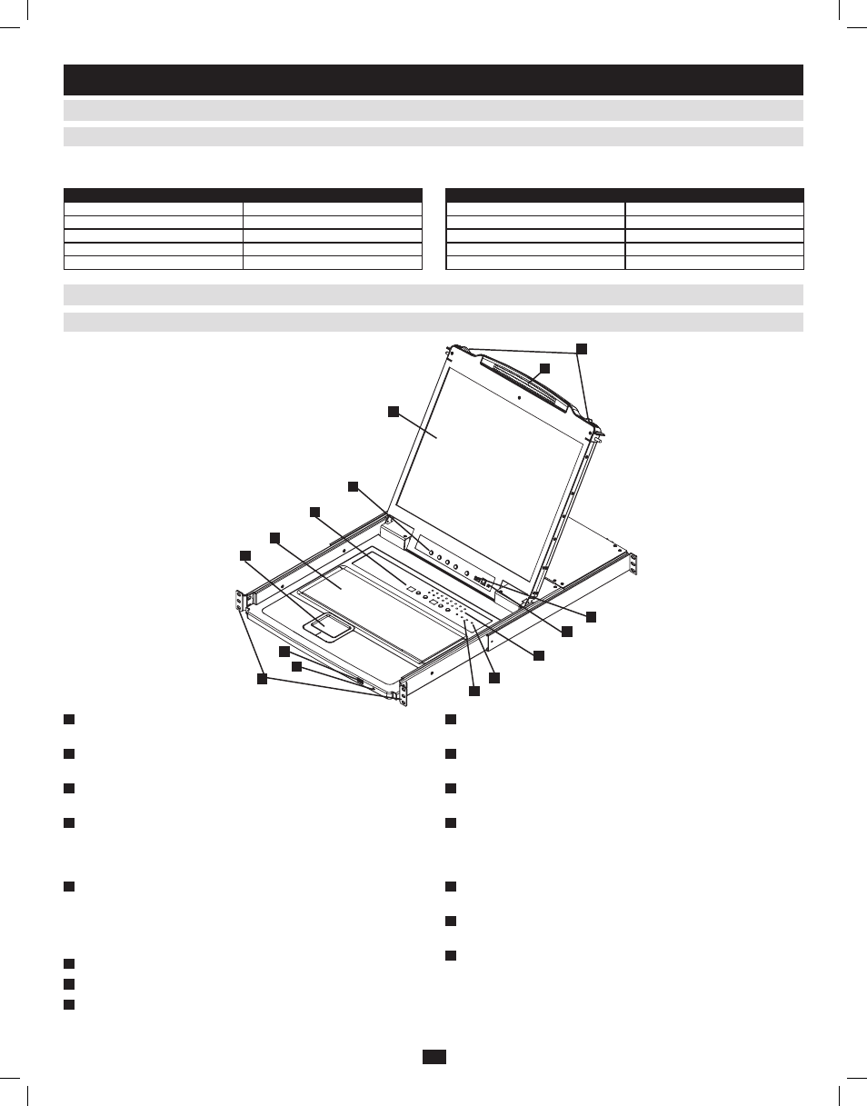
4.4 Components
1
Handle: Pull to slide the KVM module out; push to slide the KVM
module in. (See item 13.)
2
LCD Display: After sliding the KVM module out, flip up the cover to
access the LCD monitor.
3
LCD Controls: The LCD ON/OFF switch is located here, as well as
buttons to control the position and picture settings of the LCD display.
4
Station/Port Switches: Press the Port ID Up/Down buttons to switch
to the port before/after the currently selected port. Press the Station
ID Up/Down buttons to switch to the station before/after the currently
selected station.
5
LEDs: The Online Port LEDs illuminate orange to indicate a
computer is connected and powered on. The Port ID LED will display
the number of the port that currently has the console’s focus. The
Station ID LED will display the number of the station that currently
has the console’s focus.
6
Keyboard
7
Touchpad
8
Power LED: The Power LED illuminates blue to indicate the unit is
receiving power.
9
Rackmounting Tabs: The rackmounting tabs located at each corner
of the unit secure the chassis to a system rack.
10
Lock LEDs: The Num Lock, Caps Lock and Scroll Lock LEDs are
located here.
11
Reset Switch: Press this recessed switch in with a thin object to
perform a system reset.
12
Firmware Upgrade Section: The firmware upgrade cable that
transfers the firmware upgrade data from the administrator’s computer
to the console KVM switch connects to the port located here. During
normal operation, this switch should be in the NORMAL position.
13
Slide Release: In order to bring the console out, you must first release
it by sliding these tabs to the inside.
14
External Mouse Port: An additional USB port is provided on the
front panel of the keyboard module for an option external mouse.
15
USB Peripheral Port: A USB 1.1 port is provided for the sharing of
USB peripherals among connected computers (e.g. flash drive, CD-
ROM drive, etc.).
4.4.1 Front View
2
3
4
6
7
8
9
5
10
11
12
13
1
14
15
201009236 93-2985.indd 5
11/18/2010 4:21:33 PM