Installation – Tripp Lite B020-U08-19-IP User Manual
Page 10
B020-U08-19-IP
10
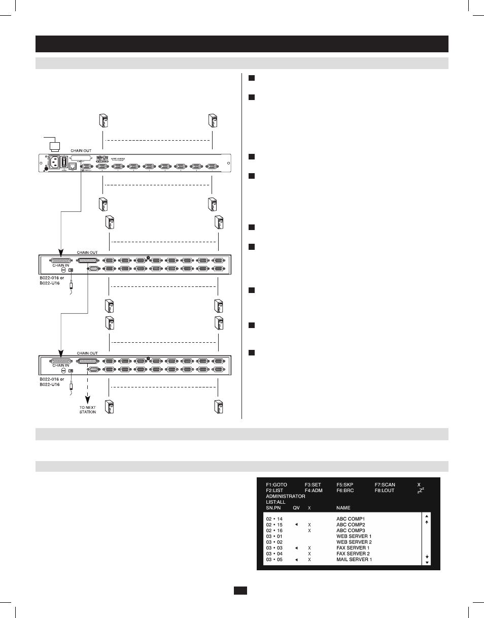
5.8 Multi-Stage Daisy-chain Installation
5.9 Network Setup-IP Address Configuration
5. Installation
(continued)
The number of connected computers can be increased by daisy-chaining
additional B022-016 or B022-U16 KVM Switches. Up to 504 computers
can be connected by daisy-chaining an additional 31 KVM switches off of
the first stage unit.
In order to configure a fixed IP address, you will need to access the KVM switch in one of three ways; Local Console, IP Installer or Browser.
1
Power OFF all computers that are being connected to the KVM
switch.
2
Using a P772-Series Daisy-Chain Cable (sold separately), connect
the Chain Out port on the back of the first stage KVM to the Chain
In
port on the back of the next stage KVM. The distance between any
two KVM switches in a daisy-chain must not exceed 49 ft. (15 m).
The distance between the first KVM switch and the last KVM switch
in a daisy-chain must not exceed 328 ft. (100 m), regardless of the
number of KVM switches in the entire chain.
3
Repeat step 2 for each additional KVM switch you wish to add to the
installation, with a maximum of 32 levels.
4
Connect a P778-Series USB/PS2 Combo KVM Cable Kit between an
available KVM port and a computer/server. P778-Series Cable Kits
allow you to connect to a computer with either USB or PS/2*
keyboard/mouse ports, without the need for separate cables. Note:
The distance between the KVM and the connected computer must not
exceed 33 ft. (10 m).
5
Repeat step 4 for each additional computer/server you wish to add to
the installation.
6
Connect the included power cord to the C14 jack on the back of the
first stage unit, and then plug it into a Tripp Lite Surge Suppressor,
PDU or Uninterruptible Power Supply (UPS). Turn on the first stage
KVM switch. The Station ID on the KVM’s keyboard panel will
display 01.
7
Connect the external power supply included with the next stage
KVM switch and plug it into a Tripp Lite Surge Suppressor, PDU or
Uninterruptible Power Supply (UPS). The Station ID on the KVM’s
front panel will display 02.
8
Repeat step 7 for each subsequent KVM switch in the installation.
In each case, wait for the previous KVM switches Station ID to be
displayed before connecting the power cord to the next KVM switch.
9
Power ON the connected computers.
*When connecting to computers using the PS/2 connectors of a P778-Series Cable Kit, the
Mouse Sync Mode setting must be set to Manual in order to access the computer over IP. If
Mouse Sync Mode is set to Automatic, you will not have mouse functionality when accessing
that computer over IP. This setting is set to Manual by default. (See page 51 for details on
changing this setting via the Web Management Interface, or page 41 to change it via the
Remote OSD.)
5.9.1 Local Console
1. When accessing the console KVM switch for the first time, a prompt
will appear asking for a Username and Password. The default User-
name
is administrator, and the default Password is password. For
security purposes, it is strongly recommended that you change the
username and password on this account to something unique. (See
User Management on page 33 for details.) When you have entered
your username and password, the OSD will appear with the following
page displayed.
201009236 93-2985.indd 10
11/18/2010 4:21:35 PM