4100u fan control module, Overview, Labeling – Tyco 4100U User Manual
Page 142: Mounting & connection, Programming, 4100u fan control module -4, Overview -4, Labeling -4, Mounting & connection -4, Programming -4
10-4
ME0456 is a 4100U style Switch/LED display module specifically designed for fan
control. It complies with the requirements of AS1668.1, 1998. It has rotary switches and
LEDs for 4 fans. In order to accommodate the required rotary switches, the front plate is
joggled forward so that it protrudes through the trim.
The Fan Control switch positions of ON, AUTO and OFF, as per the standard, are
permanently marked on the faceplate label.
The labeling of the LEDs, ON, FLT, and OFF is marked on the removable fan name label
card, LB0605, supplied with the module.
The card may be reversed and different LED labelling used, e.g. as required for damper
controls.
The name area accommodates 3 rows of 6 letters at 5mm.
A “soft” version of this label is available on the TSP website as LB0605. This template
allows entry of the fan name on a PC for local printing. LED names may also be revised.
The Fan Control module mounts to the frame of the 4100U Expansion bay door, from the
front, by the studs on the module with the nuts and washers provided.
Connection from “Out” of the adjacent Switch/LED module (or 64/64 Controller if it is
the first module on that Controller) to “In” on the module is by the flat flexible cable
provided (SX0039).
The Module is programmed as a standard 8 Switch/16 LED module. Up to 4 can be
driven by one 64/64 Switch/LED Controller.
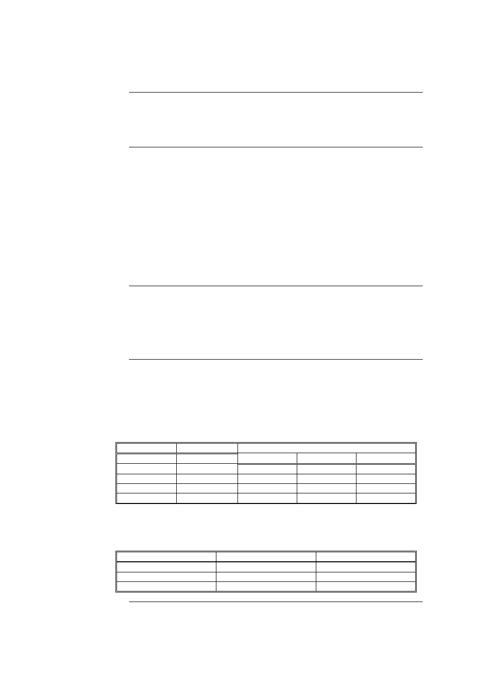
Each fan control with one rotary switch uses two of the 8 “switches”, and 3 of the 16
LEDs of an 8 Switch/16 LED module as per Table 1. The other 4 LEDs are not fitted so
must not be programmed.
Table 10-1. Switch/LED Format
Fan Control
Switches
LEDs
ON
FLT
OFF
1 SW1,
SW2
LD1 LD2 LD3
2 SW3,
SW4
LD5 LD6 LD7
3 SW5,
SW6
LD9 LD10 LD11
4 SW7,
SW8
LD13 LD14 LD15
The switch functions for Fan Control 1 are shown in Table 2. The state with both switches
closed is not physically achievable.
Table 10-2. Switch Status
SW1 SW2
Control
Status
Closed (up)
Open (centre)
On
Open (centre)
Closed (up)
Off
Open (centre)
Open (centre)
Auto
Continued on next page
4100U Fan Control Module
Overview
Labeling
Mounting &
Connection
Programming