Making audio measurements – Tektronix 1740A/1750A User Manual
Page 96
Basic Measurements
1740A/1750A Series Waveform/Vector Monitor User Manual
4-15
Making Audio Measurements
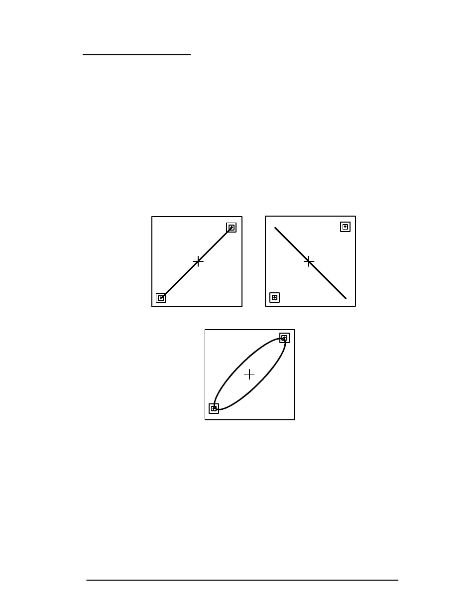
An audio signal with no phase error appears as a straight line
extending from the audio box in the upper right corner of the
graticule to the box in the lower left. A signal with phase
error appears as an opening in a Lissajous waveform.
Figure 4-13 shows three audio input signals that are equal in
amplitude, but have different phase relationships.
Audio gain is set from the
GAIN
menu when
AUDIO
display is
selected. Gain choices are 0 dBu, 4 dBu, 8 dBu, or 12 dBu.
Select gain relative to the system under test.
a. Correct Phase
b. Phase Error of 180°
c. Phase Error of approximately 30°
Figure 4-13. Audio displays.