Selection procedure – Trane RT-PRC010-EN User Manual
Page 17
17
RT-PRC010-EN
Selection
Procedure
ITD = 190 F - 65.4 F = 125 F. Divide the
winter heating load by ITD = 563 MBh ÷
125 F = 4.50 Q/ITD.
From Table PD-31, select the low heat
module. By interpolation, a Q/ITD of 4.50
can be obtained at a gpm at 25.7.
Water pressure drop at 25.7 gpm is 0.57
ft. of water. Heat module temperature
rise is determined by:
Total Btu =
∆
T
1.085 x Supply cfm
563,000 = 29.7 F
(1.085 x 17,500)
Unit supply air temperature = mixed air
temperature + air temperature rise = 65.4
+ 29.7 = 95 F.
Steam Heating System
Assume a 15 psig steam supply.
From Table PD-27, the saturated
temperature steam is 250 F. Subtract
mixed air temperature from the steam
HEATING CAPACITY SELECTION
Step 1 — Determine Air Temperature
Entering Heating Module
Mixed air temperature = RADB + % OA
(OADB - RADB) = 70 + (0.10) (0 - 70) = 63
F
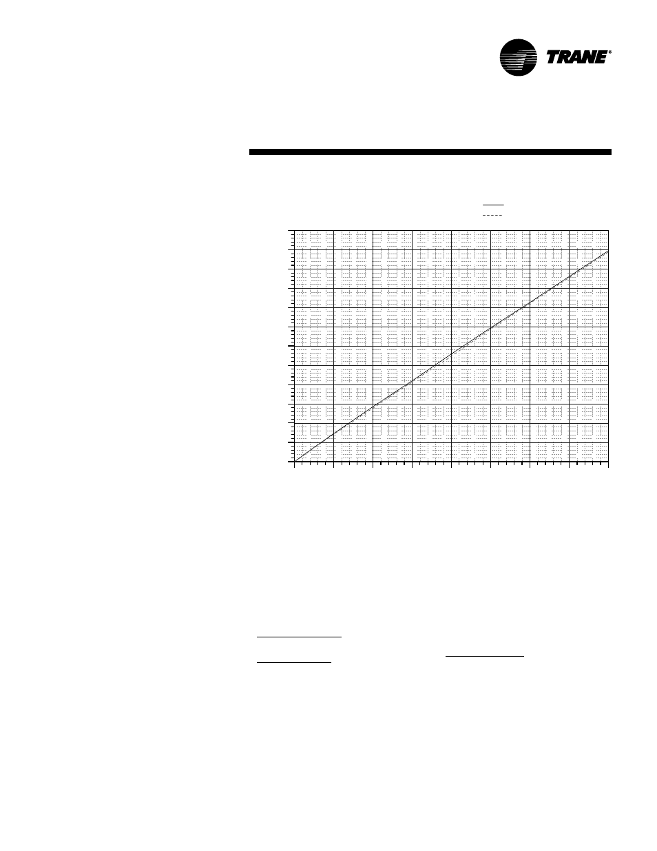
Supply air fan motor heat temperature
rise = 46,000 Btu ÷ (1.085 x 17,500 cfm) =
2.42 F
Air temperature entering heating
module = 63.0 + 2.42 = 65.4 F
Step 2 — Determine Total Winter Heating
Load
Total winter heating load = peak heating
load + ventilation load - supply fan
motor heat = 475 + 133 - 46.0 = 562 MBh
Electric Heating System
Unit operating on 460/60/3 power supply.
From Table PD-30, kw may be selected
for a nominal 50 ton unit operating
460-volt power. The 170 kw heat module
(580.1 MBh) will satisfy the winter
heating load of 563 MBh.
Table PD-28 shows an air temperature
rise of 30.6 F for 17,500 cfm through
the 170 kw heat module.
Unit supply temperature at design
heating conditions = mixed air
temperature + air temperature rise = 65.4
F + 30.6 F = 96.0 F.
Gas Heating System (Natural Gas)
From Table PD-24 select the high heat
module (697 MBh output) to satisfy
winter heating load of 563 MBh at unit
cfm.
Table PD-26 also shows an air
temperature rise of 36.0 F for 17,500 cfm
through the heating module.
Unit supply temperature at design
heating conditions = mixed air
temperature + air temperature rise = 65.4
F + 36.0 F = 101.4 F.
Hot Water Heating
Assume a hot water supply temperature
of 190 F. Subtract the mixed air
temperature from the hot water
temperature to determine the ITD (initial
temperature difference).
temperature to determine ITD. ITD = 250
F - 65.4 F = 185 F.
Divide winter heating load by ITD =
563 MBh ÷ 185 F = 3.04 Q/ITD.
From Table PD-26, select the high heat
module. The high heat module at 17,500
cfm has a Q/ITD = 5.11.
Heat module capacity, Q = ITD x Q/ITD =
185 F x 5.11 Q/ITD = 945 MBh
Heat module air temperature rise
= Total Btu
1.085 x Supply cfm
945 Btu ÷ (1.085 x 17,500 cfm) = 49.8 F.
Unit supply temperature at design
conditions = mixed air temperature + air
temperature rise = 65.4 F + 49.8 F = 115 F.
Chart SP-1 — Fan Motor Heat
0
5
10
15
20
25
30
35
40
0
10
20
30
40
50
60
70
80
90
100
110
120
STANDARD MOTOR
HIGH EFFICIENCY MOTOR
F
A
N
M
O
T
O
R HE
A
T
-
M
B
H
MOTOR BRAKE HORSE POWER