2 details of the dm642 code and control registers, 1 dm642 control window, Registers – Texas Instruments TVP5154EVM User Manual
Page 26: Window
www.ti.com
9.2
Details of the DM642 Code and Control Registers
9.2.1
DM642 Control Window
Programming the TMS320DM642
Details of the DM642 code and control registers are:
•
The DM642 device address is 0x40h by default. The DM642 is setup as an I
2
C slave.
•
The DM642 executes code on power up from the flash using the PCI GPIO to control the address
MSB.
•
Virtual I
2
C registers are created within the DM642 in order to control the capture and display of the
scaled/unscaled data from the TVP5154 video decoder. These registers are described in
•
The virtual I
2
C registers support scaled and unscaled video outputs independently for each of the four
video decoders, with the option to overlay scaled video onto unscaled video, and to define the
quadrant location of each scaled channel.
•
The virtual I
2
C registers provide easy control/access to the GPIOs currently tied to LEDs. Please refer
to the TVP5154EVM schematics for options to associate an LED on/off with a register setting.
•
The DM642 is not responsible for any scaling. All video scaling is performed by the TVP5154. The
DM642 is only responsible for image capture and display.
•
The DM642 virtual registers can be controlled by using the DM642 Control Window or through the
Generic I
2
C registers.
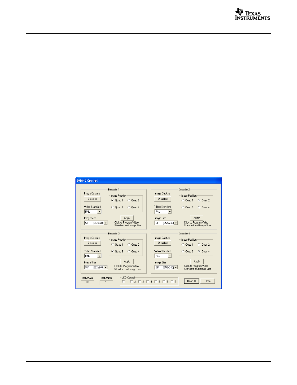
The DM642 settings can be easily controlled by using the DM642 Control window. This window represents
the DM642 register data in a user-friendly format. The data is organized for each of the four decoders (see
).
To open this, click on DM642 Control in the Tools menu.
Figure 21. DM642 Control Window
26
TVP5154EVM User's Guide
SLEU069A – February 2006 – Revised July 2006