Toshiba RAV-SM1100UT-E User Manual
Page 77
74
Installation Pr
ocedure
•
F
or installation of the adapter P
.C
. board and remo
v
al of the rela
y cab
le
, be sure to w
ait f
or a while (appro
x
. 1 min
ute) after
tur
ning off the po
w
er supplies of the air conditioner and the collectiv
e control remote controller
. If not doing so
, the adapte
r
P
.C
. board ma
y be damaged.
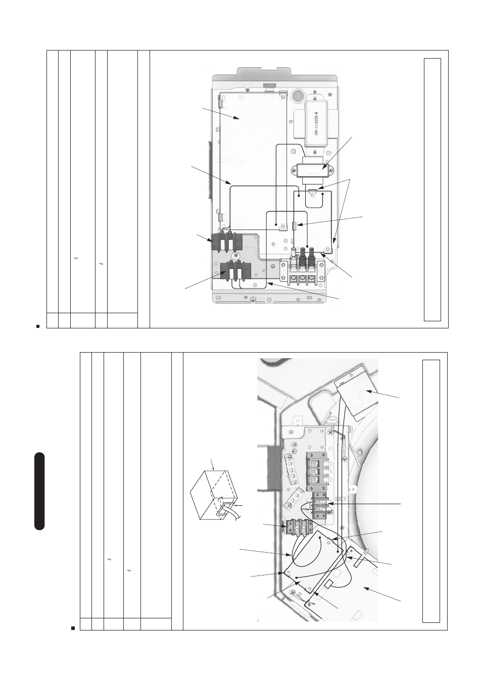
In case of 4-wa
y Ceiling Cassette (RA
V
-SM
**
0 UT
-E)
Rela
y cab
le (A)
Rela
y cab
le (B)
CN02
(Blue)
CN03
(Red)
CN01
(White)
CN309
(Y
ellow)
Spacer (C)
Spacer (C)
Spacer (C)
Indoor P
.C
. board
A, B ter
minal b
loc
k f
or remote controller
T
ransf
or
mer bo
x
X,
Y rela
y ter
minal b
loc
k
Network adapter
P
.C
. board
No.
1
2
3
4
Pr
ocedure
Using the spacer (C), install the adapter P
.C
. board to the position of the electr
ic par
ts bo
x of the indoor unit.
Using the 2 pcs
.
Ø
4 x 14
tapping tight scre
w
s
, install X,
Y rela
y ter
minal b
loc
k to the position of the
electr
ic par
ts
b
o
x
.
•
When tightening the scre
w
s
, be sure not to damage the cab
le
.
Using 2 pcs
.
Ø
4 x 6
tapping scre
ws
, install the transf
o
rmer bo
x stor
ing the tr
ansf
o
rmer to the position at side of the
bell mouth.
Using the rela
y cab
le (A), connect the X,
Y rela
y ter
minal b
loc
k with CN03 (Red) of the adapter P
.C
. board, and
remot
e
controller
ter
minal b
loc
k (A, B) with CN02 (Blue) of the adapter P
.C
. board using the rela
y cab
le (B), respectiv
ely
.
P
erf
o
rm cab
ling betw
een the y
ello
w connector of the tr
ansf
o
rmer and CN309 of the adapter P
.C
. board, and betw
een
white connector to CN01 of the adapter P
.C
. board, respectiv
ely
.
Details
Adapter TCB-PCNT20E
sold
separ
ately
*
T
o install the adapter P
.C
. board to the electr
ic par
ts bo
x, put 3 pcs
. spacer (C) into the hole of the P
.C
. board.
*
After connection of the rela
y cab
les (A) and (B), fix them along the neighboring cab
les with b
undling band so that
cab
les are not caught.
CA
UTION :
Be sure that lead wire of the tr
ansf
or
mer
is not caught in between the tr
ansf
or
mer
c
o
v
er and the transf
or
mer base
.
T
ransf
or
mer base
T
ransf
or
mer co
v
e
r
In case of Concealed Duct (RA
V
-SM
**
0 BT
-E)
CN309 (Y
ellow)
A, B ter
minal b
loc
k f
or remote controller
Rela
y cab
le (A)
Spacer (B) 1 pc.
Network adapter P
.C
. board
T
ransf
or
mer f
or network adapters
Spacer (A) 2 pcs
.
Rela
y cab
le (B)
X,
Y rela
y ter
minal b
loc
k
Indoor P
.C
. board
38001
CN02
(Blue)
CN03
(Red)
CN01 (White)
No.
1
2
3
4
Pr
ocedure
Using the spacer (A) and (B), install the adapter P
.C
. board to the position of the electr
ic par
ts bo
x
.
Using the 2 pcs
. Ø
4 x 14
tapping tight scre
ws
,
install X,
Y rela
y ter
minal b
loc
k to the position of the electr
ic par
ts bo
x of
the indoor unit.
•
When tightening the scre
ws
, be sure not to damage the cab
le
.
Using 2 pcs
.
Ø
3 x 6
B-tight
scre
ws
,
install the tr
ansf
or
mer to the position of the electr
ic par
ts bo
x of the indoor unit.
Using the rela
y cab
le (A), connect the X,
Y rela
y ter
minal b
loc
k with CN03 (Red) on the adapter P
.C
. board, and
remote controller ter
minal b
loc
k (A, B) with CN02 (Blue) on the adapter P
.C
. board using the rela
y cab
le (B), respectiv
ely
.
P
erf
or
m cab
ling between the y
ello
w connector of the transf
or
mer and CN309 on the indoor P
.C
.board, and betw
een
white connector and CN01 on the adapter P
.C
. board, respectiv
ely
.
Details
Adapter TCB-PCNT20E
sold
separ
ately
•
Rela
y cab
le (A):
Connection between X,
Y ter
minal b
loc
k and CN03 on the adapter P
.C
. board
•
Rela
y cab
le (B):
Connection betw
een ter
minal b
loc
k of the remote controller and CN02 on the adapter P
.C
. board
*
T
o install the adapter P
.C
. board to the electr
ic par
ts bo
x, put 2 pcs
. spacers (A) into the hole of the P
.C
.board
(At upper side and at lo
wer r
ight side of the P
.C
.board), and install one of them to the electr
ic par
ts bo
x
(At lo
w
er left side of the P
.C
.board) using the board installing spacer (B) of a type which pinches the P
.C
.board.
* After connection of the rela
y cab
les (A) and (B), fix them along the neighbor
ing cab
les with b
undling band so that
cab
les are not caught.