Inst alla tion manu al, Netw ork adapter f or air conditioner – Toshiba RAV-SM1100UT-E User Manual
Page 76
73
INST
ALLA
TION MANU
AL
Netw
ork Adapter f
or Air Conditioner
Use f
or Indoor Unit Onl
y
MODEL :
TCB-PCNT20E
[For Installation Pr
of
essionals]
•
Thank y
ou f
or purchasing the par
ts sold separately f
or
T
OSHIBA pac
kage air conditioner
.
•
Bef
ore installation wor
k, please read this manual thoroughly and install the products correctly
.
•
Ensure that all Local, National and Inter
national regulations are satisfied.
•
Read this
“CA
UTION SAFETY
” carefully bef
ore Installation.
•
The precautions descr
ibed below include the impor
tant items regarding saf
ety
.
CA
UTIONS f
or SAFETY
W
ARNING
•
Ask an authoriz
ed dealer or qualified installation pr
ofessional to install/maintain the air conditioner
.
Inappropr
iate installation ma
y result in w
ater leakage
, electr
ic shoc
k or fire.
•
T
urn off the main po
wer supply s
witc
h or breaker bef
ore attempting an
y electrical w
ork.
Mak
e sure all po
wer s
witches are off
. F
ailure to do so ma
y cause electr
ic shoc
k
.
•
Connect the connecting cable correctl
y
.
If the connecting cab
le is connected in a wrong w
a
y,
electr
ic par
ts ma
y be damaged.
•
When mo
ving the air conditioner f
or the installation into another place
, be ver
y careful not to enter an
y gaseous
matter other than the specified refrigerant into the refrig
eration c
y
c
le
.
If air or any other gas is mix
ed in the refr
iger
ant, the gas pressure in the refr
iger
ation cycle becomes abnor
mally high and
it ma
y resultingly causes pipe b
urst and injur
ies on persons
.
•
Do not modify this unit b
y
remo
ving an
y of the saf
ety guar
ds or b
y
b
y-passing an
y of the saf
ety interloc
k s
witc
hes.
•
Exposure of unit to water or other moisture bef
ore installation
ma
y cause a shor
t-cir
cuit of electrical par
ts.
Do not store it in a wet basement or e
xpose to rain or w
ater
.
CA
UTION
•
Using the specified cab
les
, surely so that the e
xter
nal f
orce of the cab
le is not tr
ansmitted to the ter
minal connecting
section, otherwise disconnection, heating, or fire ma
y be caused.
•
Do not apply an e
xcessiv
e
f
orce on the board body
, otherwise bending, separation, or disconnection gener
ates resulted
in heating or fire
.
•
After installation
w
o
rk, e
x
ecute a test r
un to confir
m there is no troub
le
.
And also ask the customer
s to keep this Manual b
y
themselves.
Components
P
a
rt
name
P.
C
. board
Rela
y ter
minal b
loc
k
Rela
y cab
le (A)
Rela
y cab
le (B)
Installation Man
ual
Spacer (A)
Spacer (B)
Spacer (C)
Scre
ws to fix ter
minal b
loc
k
T
ransf
or
mer cov
e
r
T
ransf
or
mer base
T
ransf
or
mer
Scre
ws to fix transf
or
mer
Scre
ws to assemb
le tr
ansf
or
mer cov
e
r
Scre
ws to fix tr
ansf
or
mer base
Bundling band
Q
’ty
1
1
1
1
1
2
1
3
2
1
1
1
2
2
2
3
Description
P
.C
. board corresponded to the netw
or
k
2P (X,
Y) ter
minal
b
loc
k f
or rela
y
F
or connection of adapter board with X,
Y rela
y ter
minal b
loc
k (Red connector)
F
or connection
of adapter board with remote controller
ter
minal b
loc
k (Blue connector)
This man
ual
F
or fixing the adapter P
.C
. board
(Used f
or other types than 4-w
a
y
cassette type)
F
or fixing the adapter P
.C
. board
(Used f
or other types than 4-w
a
y
cassette type)
F
or fixing the adapter P
.C
. board
(Used f
or 4-w
a
y
cassette type)
F
or fixing the rela
y ter
minal b
loc
k (M4 x 14
)
Used to store transf
or
mer (F
or 4-w
a
y
cassette type)
Used to store transf
or
mer (F
or 4-w
a
y
cassette type)
F
or supplying po
w
er to adapter
F
or fixing tr
ansf
o
rmer (M3 x 6
)
F
or assemb
ling tr
ansf
or
mer co
v
er (M4 x 6
f
or 4-wa
y
)
F
or fixing tr
ansf
or
mer base (M4 x 10
f
or 4-wa
y
)
Used to process cab
les so that the
y are not caught in.
10mm
18mm
10mm
A
B
C
Combination List of Adapter P
a
rt
s
1
2
3
4
5
6
7
For 4-wa
y type
3 spacers (C) f
or installing P
.C
. board
M3 x 6 B tight scre
w (2 pcs
.)
M4 x 6 tapping scre
ws (2 pcs
.)
M4 x 10 plus tight scre
ws (2 pcs
.)
M4 x 14 tapping tight scre
ws (2 pcs
.)
Connector
, red color
, lead length :
600L
Connector
, b
lue color
, lead length :
600L
Pa
rt
s
Adapter P
.C
. board
T
ransf
or
mer
F
or assemb
ling trans
fo
rmer co
v
e
r
F
or fixing transf
or
mer base
XY ter
minal b
loc
k
Adapter P
.C
. board to XY ter
minal b
loc
k
Adapter P
.C
. board to AB ter
minal b
loc
k
For Concealed duct type
2 spacers (A) f
or installing P
.C
. board
1 spacer (B) f
or installing P
.C
. board
M3 x 6 B tight scre
w (2 pcs
.)
———
———
M4 x 14 tapping tight scre
ws (2 pcs
.)
Connector
, red color
, lead length :
600L
Connector
, b
lue color
, lead length :
600L
*
Spacer (A) f
or installing P
.C
. board :
Spacer to be mounted b
y
using the hole on the P
.C
. board.
(F
or other types than 4-w
a
y
cassette type)
Spacer (B) f
or installing P
.C
. board :
Spacer to be mounted b
y
pinching it in the P
.C
. board.
(F
or other types than 4-w
a
y
cassette type)
Spacer (C) f
or installing P
.C
. board :
Spacer to be mounted b
y
using the hole on the P
.C
. board f
or 4-w
a
y
cassette type
.
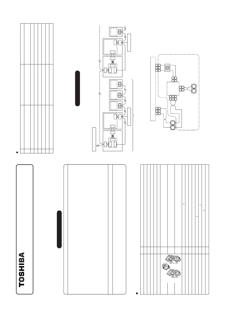
Connection of Cab
les
1.
Connection of netw
ork cab
les
•
Attach one netw
or
k adapter to a group of one group controlling (including one unit).
Connect the netw
or
k adapter to an
y one of the indoor units in the g
roup control.
X
Y
Central remote controller
Remote controller
Non polar
ity cab
le
Connectab
le indoor units per group :
Up to 8 units (In case of 1-remote controller system
*
)
*
In case of 2-remote controllers system, up to 7 indoor units are allo
w
a
b
le to be connected.
Non polar
ity cab
le
Non polar
ity cab
le
Non polar
ity cab
le
A
B
In
do
or
co
nt
ro
l
P
.C
.bo
ar
d
Indoor unit
Indoor
unit
Indoor unit
controll
P
.C
.board
A
B
In
do
or
co
nt
ro
l
P.
C
.b
o
a
rd
Indoor unit
A
B
In
do
or
co
nt
ro
l
P.
C
.b
o
a
rd
Indoor unit
Remote controller
1
2
CN03
CN02
CN041
CN041
2
1
3
1
1
3
3
1
1
3
A
B
X
Y
AB
In
do
or
co
nt
ro
l
P
.C
.bo
ar
d
Indoor unit
Indoor
unit
Indoor unit
controll
P
.C
.board
1
2
CN03
CN02
CN01
CN01
CN309
CN309
2
1
3
1
1
3
3
1
1
3
A
B
2.
Cab
ling dia
gram of indoor contr
ol P
.C.
boar
d
•
F
or details, see the installation procedure f
or individual model.
1
1
2
2
A
B
1
1
2
2
3
2
3
2
1
1
3
3
1
1
2
2
3
3
2
2
1
1
X
Y
Blac
k
Blac
k
White
Blac
k
Gra
y
Gra
y
CN01 (White)
CN02 (Blue)
CN041 (Blue)
CN309 (Y
ellow)
CN03 (Red)
Network connection ter
minal b
loc
k
Network
adapter
P
.C
. board
Indoor contr
ol P
.C.
boar
d
T
e
rminal b
loc
k
for connecting
remote controller
Po
w
e
r
supply
tr
ansf
or
mer
•
The enclosed section with the chain line includes the attached par
ts
.
•
There is no polar
ity f
or cab
ling to the ter
minal b
loc
ks
, A, B and X,
Y
.
•
Arr
ange the total cab
le length of the remote controller cab
le and the inter-unit cab
le of the remote controller within 400m.