Inst alla tion manu al – Toshiba RAV-SM1100UT-E User Manual
Page 70
67
INST
ALLA
TION MANU
AL
Lead wires
pull-out
part at lower
case
Fixed part of
lead wires
Remote controller cord
(sold separately)
Connector
Wood screws
(2 pcs.)
T
e
rminal bloc
k f
or
remote controller
cable in indoor unit
A
B
Appro
x.
200mm
W
: White
B
: Black
W
B
Remote controller cable
(Procured locally)
Cable from
remote controller body
Connecting
section
Remote
controller
Attached
wire joint
(White,
2 pcs.)
T
o
P
e
rsonnel Char
ged in Installation (Electric)
W
ork and Service
Standar
d Remote Contr
oller
MODEL : RBC-AMT21E
Accessor
y par
ts
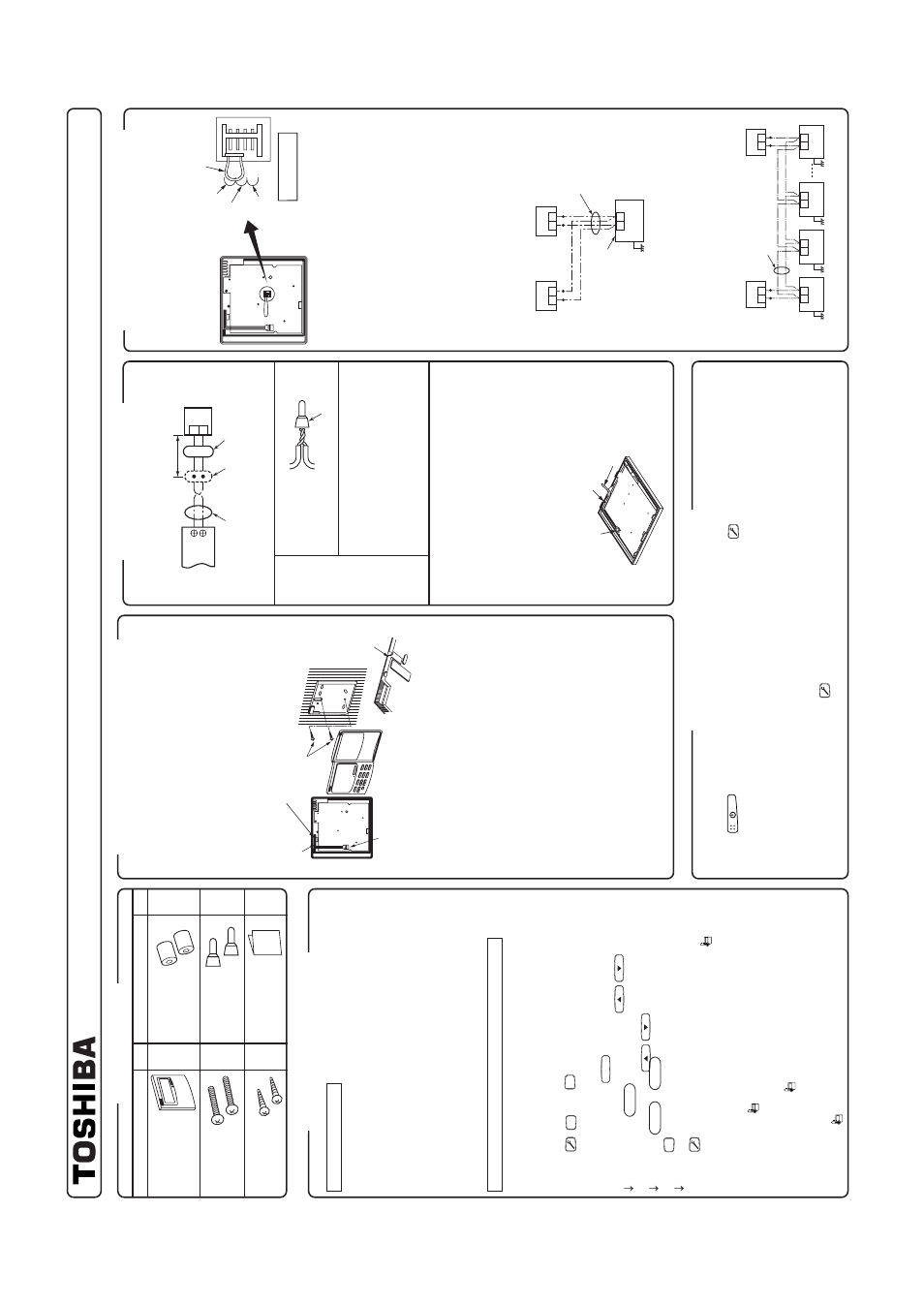
Ho
w to install remote contr
oller
NO
TE 1 :
A
v
oid to twist the remote controller cab
le with
po
w
er supply cab
le
, etc.
or to store them in
the same metal pipe
, otherwise it causes a
malfunction.
NO
TE 2 :
Install the remote controller apar
t from the
gener
ation source of noise
.
NO
TE 3 :
When noise is contained to the unit po
wer
supply
, counter measures such as mounting
the noise filter is necessar
y.
•
When using the remote contr
oller as e
xposed,
install it at the wall surface where it can be fix
ed.
Fig. A
1.
F
or remo
val and mounting of the remote controller
body and the rear case
, ref
er to the item,
“Using as
concealed type
”.
2.
Remov
e
the lead wires w
ound to the fixing par
t of
lead wires of the remote controller body
, remo
v
e
the
connectors, and then connect the remote controller
cab
le (sold separ
ately) to the connector section of the
remote controller body
. Inser
t the remote controller
cab
le into the g
roo
v
e
and f
o
rm
it, and wind it around
the fixing par
t of lead wires
.
Notching the lo
w
er case (thin par
t of the upper center
par
t) with nipper
, etc., pull out the remote controller
cab
les from this par
t.
(Fig.
A) (Ref
er to the item,
“Ho
w
to perf
or
m cab
ling of the remote controller
”.)
Connect
cab
les of the remote contr
oller after
c
hec
k of terminal No.
of the indoor unit so that
there is no mis
wiring.
(Do not appl
y A
C
200/230/
240V to the remote contr
oller
.)
3.
Fix the remote controller body b
y
two w
ood scre
ws
.
4.
Using the cab
le clips (Accessor
y of remote controller
cab
le sold separ
ately), fix the remote controller cab
le
to the wall surf
ace
.
•
Non polar
ity
, 2 core cab
le is used.
•
Use 0.5mm
² to 2mm
² cab
le.
Cable from
remote controller body
Remote controller cable
Wire joint
1)
P
eel the sheath of the cab
le to be
connected b
y
appro
x.
14mm.
2)
T
wist tw
o cab
les and pressure-connect
them using a wire joint.
3)
When an e
xclusiv
e pressure-
connecting tool is not used or solder
ing
connection is used, apply insulation
process with an insulation tape
.
•
F
or cab
ling of the remote controller
, use the
remote controller cab
le (sold separ
ately).
1.
Remo
v
e
the lead wires w
ound to the fixing par
t
of lead wires of the remote controller body
,
remo
v
e
the connectors
, and then connect the
remote controller cab
le (sold separ
ately) to the
connector section of the remote controller body
.
Inser
t the remote controller cab
le (sold
separ
ately) into the g
roo
ve
and f
o
rm
it, and wind
it around the fixing par
t of lead wires
.
2.
When using the remote controller cab
le (sold
separ
ately), ref
er to the Installation Man
ual
attached to the remote controller cab
le.
Connector
Fix
ed par
t of lead wires
Remote controller
cable
(sold separately)
Remote controller
address
Remote controller
Remote controller
address connector
Master remote controller
Remote controller
check
Sub
remote
controller
Earth
Remote controller
(Master)
Remote controller
(Sub)
2
1
(Sold separately)
T
e
rminal bloc
k f
or
remote controller cable
Remote controller cable
(Procured locally)
Indoor unit
Ear
th
Ear
th
Ear
th
(Sold
separately)
T
erminal block
for remote
controller
cable
Remote controller inter-unit
cables f
or group control
(Procured locally)
Remote controller
(Sub)
Remote controller
(Master)
Ind
oor
un
it
No
.1
B
A
Ind
oor
un
it
No
.2
B
A
Ind
oor
un
it
No
.3
B
A
Ear
th
Ind
oor
un
it
No
.N
B
A
85464359425000 (EN)
•
How to install
F
or 2 remote controllers
, install the remote
controllers in the f
ollowing procedure
.
1.
Set one of two remote controllers as the master
remote controller
. (At shipment from f
actor
y)
2.
F
or the other remote controller
, e
xchange the
remote controller address connector of the
master to sub remote controller on the P
.C
.
board. Under this condition, the other remote
controller functions as the sub controller
.
•
Basic wiring diagram
NO
TE :
Connect cab
les without mis
wir
ing.
(Mis
wir
ing breaks the unit.)
•
In a case to oper
ate an indoor unit from the
remote controllers at tw
o positions
•
In a case to oper
ate a g
roup control of m
ultiple
indoor units from the remote controllers at tw
o
positions
*
Master and Sub remote controllers are
oper
ab
le e
ven if the
y are installed to an
y
indoor unit.
Remote contr
oller test run setup
1.
When the remote controller is used at the first time
, it accepts an oper
ation appro
x.
5 min
utes after the po
w
e
r
supply has been tur
ned on.
It is not a troub
le
, b
ut is because the setup of the remote controller
is being chec
k
ed.
2.
Push
k
e
y after [TEST] has been displa
y
ed on LCD b
y
k
eeping
b
utton on the remote controller f
o
r
4 seconds or more
.
•
Dur
ing the test run, [TEST] is displa
y
ed on LCD
.
•
The temper
ature cannot be controlled if [TEST] is displa
y
ed.
Do not use [TEST] in a case other than a test r
un, otherwise an e
xcessiv
e load is applied on the machine
.
3.
Use [TEST] in one of HEA
T,
COOL, and F
AN operation modes
.
NO
TE :
The outdoor unit does
not oper
ate f
or appro
x.
3
m
in
utes after the
p
o
w
e
r
supply
has been
tur
ned on or the
oper
ation has
stopped.
4.
After the test r
un has finished, push
b
utton again to chec
k [TEST] on LCD has gone off
.
(F
or this remote controller
, a release function of 60 min
utes timer is pro
vided to pre
v
ent contin
uous test r
uns
.)
Part Name
Q
’ty
Part Name
Q
’ty
Remote controller
Screw M4 x 25
Wood screw
Spacer
Wire joint
Installation Manual
(200mm-cable attached)
1
2
2
2
2
1
Requirement f
or installation of
m
ultiple remote contr
oller
s
“2 remote controllers
” means that one or m
ultiple
units are oper
ated b
y
the m
ultiple remote
controllers
.
(Max. 2 remote controllers can be set.)
Requirement to install the
remote contr
oller
Installation place
•
Install the remote controller at a position with height 1 to 1.5m
from the floor
, where the a
ver
age temper
ature in the room can
be f
elt.
•
Do not install the remote controller at a place e
xposed to direct
sunlight or direct outside air
, such as a side of windo
w
, etc.
•
Do not install the remote controller at a place behind something
or rear side of something where air flo
w is poor in the room.
•
Do not install the remote controller in the freezing bo
x or
refr
iger
ator because water proof or drop-proof is not applied to
this remote controller
.
•
Be sure to set the remote controller v
e
rtically
on the w
all
surf
ace
, etc.
H
o
w to select the r
oom temperature sensor
The room temper
ature sensors are equipped in the indoor unit and
remote controller
.
One of two sensors w
o
rk
s
. Usually
, the room temper
ature sensor
in the indoor unit is set to w
o
rk
. T
o
select the sensor in the remote
controller side
, ref
er to the f
ollowing procedure
.
1.
K
eep
,
SET
, and
CL
b
uttons pushed f
or 4 seconds
or more
.
NO
TE)
The UNIT No
. displa
y
ed at the first time is the indoor
unit address of the master unit in the g
roup control.
NO
TE)
Do not push
UNIT
(select) b
utton.
2.
Using the temper
ature setup b
uttons
/
, specify
the item code
0032 .
3.
Using the timer b
uttons
/
, change the set
data from 0000 to 0001 .
4.
Push
SET
b
utton.
(OK if the displa
y changes from flashing to lighting)
5.
Push
b
utton.
The status retur
ns to the nor
mal status.
In this time
,
is
displa
y
ed in LCD
.
NO
TE 1 :
When using tw
o remote controllers, the master remote controller
is recognized as
sensor though the temper
ature can be set
from either master or sub remote controller
.
NO
TE 2 :
In a g
roup control, the
sensor does not w
o
rk
if the g
roup
address is not set to the indoor unit of the master unit.
NO
TE 3 :
When using the remote sensor together with the remote controller
,
do not use the
sensor of the remote controller
.
H
o
w to perf
orm cabling
of the remote contr
oller
•
Connection dia
gram