Inst alla tion manu al, Accessor y par ts, Remote contr oller test run setup – Toshiba RAV-SM1100UT-E User Manual
Page 71: Requirement to install the remote contr oller, Ho w to install the remote contr oller s witc h, Ho w to perf orm cabling of the remote contr oller
68
INST
ALLA
TION MANU
AL
Accessor
y par
ts
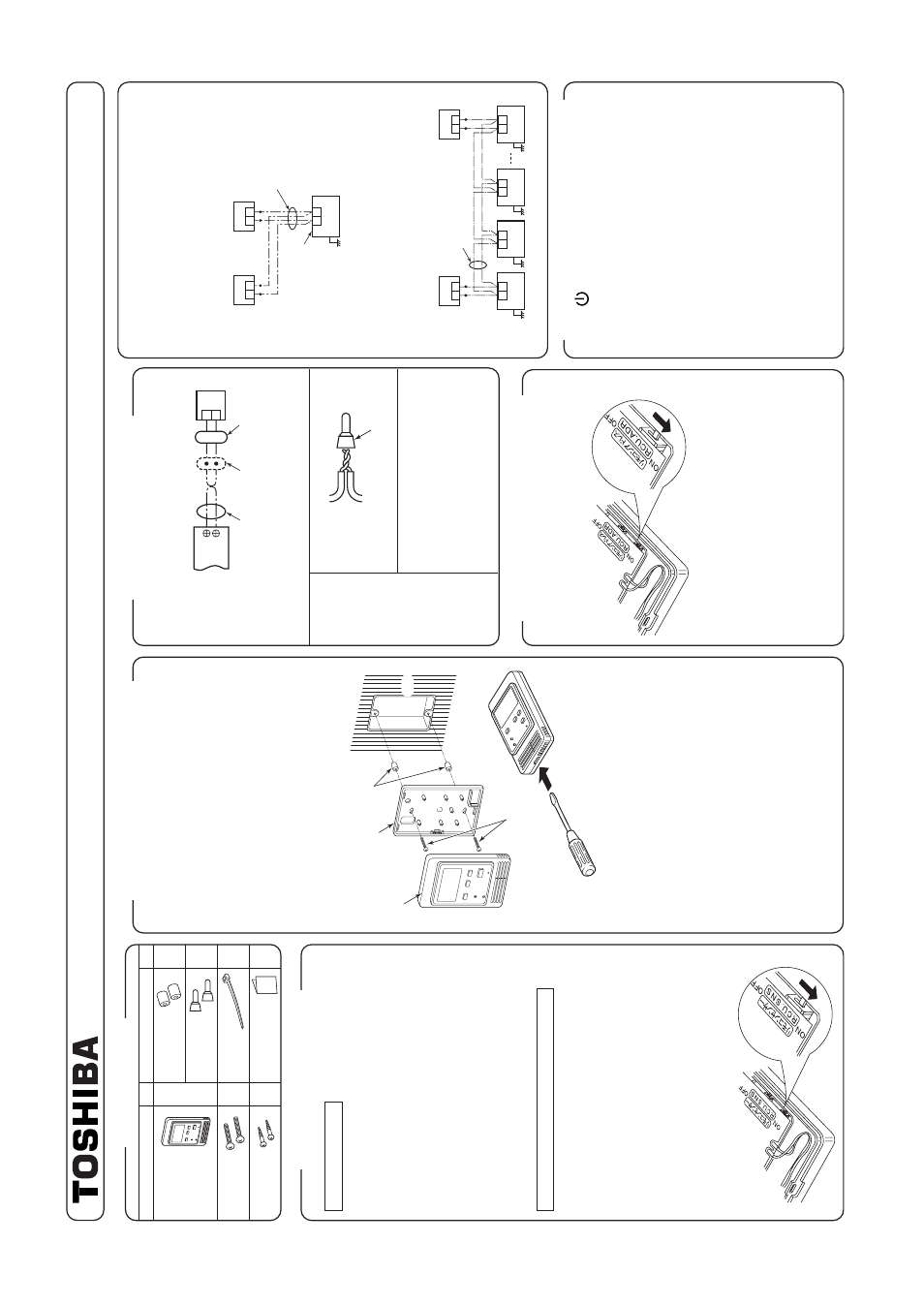
1.
Inser
ting a minus scre
wdr
iv
er
, etc.
into the
g
roo
v
e
at the lo
wer side of the remote controller
body
, f
orce open the rear case to remo
v
e
it.
2.
Using the attached M4 scre
ws (2 pcs
.), fix the
rear case of the remote controller
.
Bef
ore installation, press to open the scre
w hole
with a scre
wdr
iv
er
, etc.
Fix it with the spacer
, b
ut not so strongly
. If the
remote controller does not fit closely to the w
all,
adjust it b
y
cutting off the spacer
.
3.
Connect the remote controller cab
le (2 cores) to
the cab
le from the remote controller body
.
Connect the remote controller cab
le without
mis
wir
ing upon confir
mation of the ter
minal
n
umbers of the indoor unit.
(If applyied
A
C
220/230/240V
, ma
y damage the unit.)
4.
Install the remote controller body to hooks on the
rear case and putting into the hooks.
•
Non polar
ity
, 2 core cab
le is used.
•
Use 0.5mm
² to 2 mm
² cab
le
.
Cab
le from
remote controller body
Remote controller cab
le
Wire joint
Attached wire
joint
(White
, 2 pcs
.)
1
)
P
eel the sheath of cab
le to be connected
b
y
appro
x.
14mm.
2
)
T
wist tw
o cab
les and pressure-connect
them using a wire joint.
3
)
When an e
xclusiv
e pressure-connecting
tool is not used or solder
ing connection
is used, apply insulation process with
an insulation tape
.
•
Basic cab
ling dia
gram
NO
TE :
Connect cab
les without mis
wir
ing.
(Mis
wir
ing breaks the unit.)
•
In a case to operate an indoor unit from the
remote controllers at two positions
•
Ho
w to install
F
or 2 remote controller control, install the remote
controllers in the f
ollo
wing procedure
.
1.
Set one of the set m
ultiple remote controllers to
the master remote controller
.
(At shipment from f
actor
y
)
2.
F
or other remote controllers
, tur
n the remote
controller address s
witch on the remote controller
P.
C
. board from OFF to ON.
The
y function as sub
remote controllers under the abo
v
e
condition.
Remote contr
oller test run setup
1.
Push
k
e
y after k
eeping [CHECK] b
utton
pushed on the remote controller f
or 4 seconds or
more
.
•
Dur
ing the test r
un,
“TEST
” is displa
y
ed on
LCD
.
•
The temper
ature cannot be controlled if [TEST]
is displa
y
ed.
Do not use [TEST] in a case other
than a test r
un, otherwise an e
xcessiv
e load is
applied on the machine
.
2
.
Use [TEST] in one of HEA
T
, COOL,
and F
A
N
operation modes.
N
O
TE :
The outdoor unit does not operate f
or appro
x
. 3
min
utes after the pow
er supply has been tur
ned
on or the oper
ation has stopped.
3.
After the test r
un has finished, push [CHECK]
b
utton again to check
“
TEST
” on LCD has gone
off
.
(F
or this remote controller
, a release function
of 60 minutes timer is pro
vided to pre
v
ent
consecutiv
e test r
uns
.)
•
In a case to operate a group control of m
ultiple
indoor units from the remote controllers at tw
o
positions
*
Master and sub remote controllers are opera
b
le
e
v
en if the
y are installed to an
y indoor unit.
T
e
rminal b
loc
k f
or
remote controller
cab
le in indoor unit
A
B
W
: White
B
: Blac
k
W
B
Remote controller cab
le
(Procured locally)
Cab
le from
Remote controller
body
Connecting
section
Remote
controller
Q
’ty
1
2
2
P
a
rt
Name
P
a
rt
Name
Q
’ty
2
2
1
1
Remote controller
Scre
w
M4 x 25
(200mm-cab
le
attached)
W
ood scre
w
Spacer
Wire joint
Clamper
Installation Manual
Remote controller
body
Scre
ws
M4 x 25 or
wood scre
ws
(2 pcs.)
Rear case
Spacer
W
all
Earth
Remote controller
(Master)
Remote controller
(Sub)
B
A
(Sold separately)
T
e
rminal b
loc
k f
or
remote controller cab
le
Remote controller cab
le
(Procured locally)
Indoor unit
Ear
th
Ear
th
Ear
th
(Sold
separately)
(Sold
separately)
T
e
rminal b
loc
k
for remote
controller
cab
le
Remote controller inter-unit
cab
le f
or group control
(Procured locally)
Remote controller
(Sub)
Remote controller
(Master)
Ind
oor
un
it
No
.1
B
A
Ind
oor
un
it
No
.2
B
A
Ind
oor
un
it
No
.3
B
A
Ear
th
Ind
oor
un
it
No
.N
B
A
Requirement to install
the remote contr
oller
Installation place
•
Install the remote controller at a position within 1
to 1.5m from the floor
, where the a
v
er
age tem-
per
ature in the room can be f
elt.
•
Do not install the remote controller at a place
e
xposed to direct sunlight or direct outside air
,
such as a side of windo
w
, etc.
•
Do not install the remote controller at a place
behind something or rear side of something,
where air flo
w is poor in the room.
•
Do not install the remote controller in the freezing
b
o
x or refr
igerator because w
ater proof or drop-
proof is not applied to this remote controller
.
•
Be sure to set the remote controller v
e
rtically on
the w
all surf
ace
, etc.
Ho
w to select the r
oom temp.
sensor
The room temper
ature sensors are equipped in the
indoor unit and the remote controller
.
One of tw
o sensors wor
ks.
Usually
, the room
temper
ature sensor in the indoor unit is set to w
o
rk
.
T
o
select the sensor in the remote controller
, tur
n
the remote controller sensor from OFF to ON.
NO
TE 1 :
Selecting the sensor in the remote controller is
impossib
le on the sub remote controller
.
NO
TE 2 :
Do not select the sensor in the remote controller
when a remote controller sensor is used.
(Because it causes a str
a
ying.)
Ho
w to install
the remote contr
oller s
witc
h
NO
TE 1 :
A
v
oid to twist the remote controller cab
le with the
p
o
wer supply cab
le
, etc.
or to store them in the
same metal pipe
, otherwise it causes a malfunc-
tion.
NO
TE 2 :
Install the remote controller apar
t from the
generation source of noise
.
NO
TE 3 :
When noise is contained to the po
wer source of
the indoor unit, counter measures such as
mounting the noise filter is necessar
y.
•
In case of using the remote controller as a
concealed type
Ho
w to perf
orm cabling
of the remote contr
oller
•
Connection dia
gram
Requirement f
or installation of
m
ultiple remote contr
oller
s
“2 remote controller control
” means that one or
m
ultiple units are oper
ated b
y
the m
ultiple remote
controllers
.
T
o
P
e
rsonnel Char
g
ed in Installation (Electric)
W
ork and Ser
vice
85464359428000 (EN)
Simple Remote Contr
oller
MODEL : RBC-AS21E