Assembly, Start-up – TurboChef Technologies 3240 User Manual
Page 14
START-UP
diameter for a single oven and at least 1 inch (50.8
mm) diameter for a double or triple oven (single or
base oven) for LP or I
3P
category gas types.
8. Verify the size of the shut-off valve used. A minimum
.75-inch (19.05 mm) ID full fl ow isvalve required
for a single oven. A minimum 1-inch (25.4 mm) ID
full
fl ow valve required for a double or triple-stacked
oven.
9. Verify the size of the fl ex hose used.
- A minimum .75-inch (19.05 mm) fl ex hose is
required for single ovens.
- A minimum 1-inch (25.4 mm) fl ex hose is required
for stacked ovens.
10. Ensure a strain-relief cable is installed to a bottom
bolt hole as shown in fi gure Assembly, Step 10 below
and is correctly installed to the wall.
11. Ensure that all bolt holes in the rear of the oven are
plugged with the provided bolts, as shown below in
Assembly, Step 10.
12. For double or triple-stacked ovens, ensure that the
stacking brackets are correctly attached as shown in
Assembly, Step 11 below.
13. Ensure that each chain is set to the correct tension.
Grasp the chain as shown in Assembly, Step 12
below. The chain must have enough freedom to
move between 1/4 inch (6mm) and 3/8 inch (10mm)
to be at the correct tension. If the tension is too loose
or too tight, reset the tension.
Assembly
1. Ensure the legs are securely attached.
2. Ensure the leg bolts are tightened.
3. Ensure the window is correctly installed. Refer to
page 8 STEP 6.
4. Ensure the conveyor belt assembly is correctly
installed. Refer to page 7 STEPS 5.7-5.9.
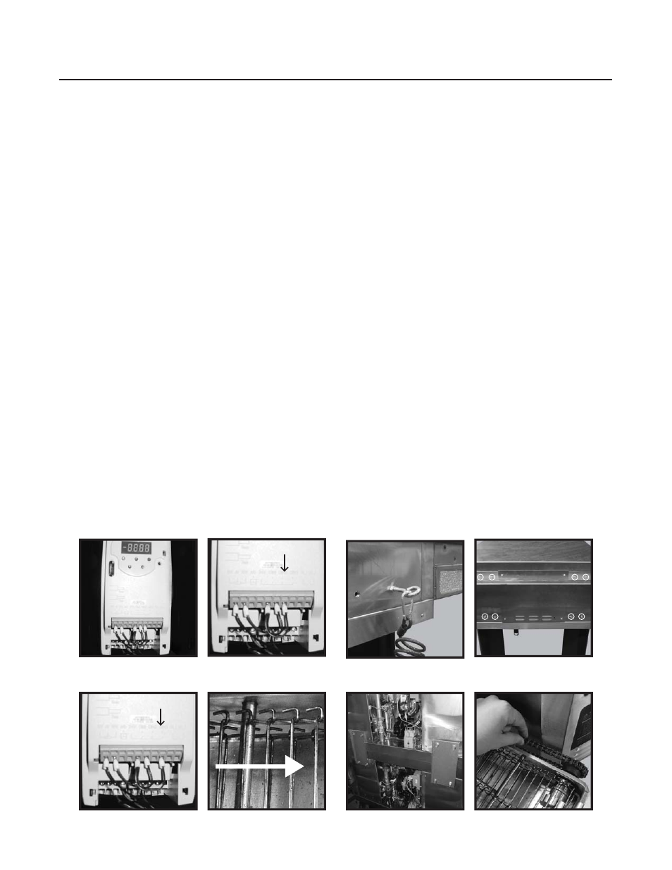
5. Verify that the oven is cofi gured to drive the belt in
the correct direction (see below illustrations).
a. Open the right end bell.
b. Remove the front panel from the CMSC.
c. Ensure the conveyor drive is set to the correct
direction.
i. For left to right confi gurations (-1), ensure
the far right wire is inserted into DIN2 as
shown in fi gure Assembly, Step 5.c.i below.
ii. For right to left confi gurations (-2), ensure
the far right wire is inserted into DIN3 as
shown in fi gure Assembly, Step 5.c.ii below.
6. Verify the direction the belt travels matches fi gure
Assembly, Step 6 below. If not, the belt must be
reversed.
7. Verify the size of the gas supply line. The gas supply
line at the appliance must be at least 1 inch
(25.4 mm) diameter for a single oven and at least 2
inch (50.8 mm) diameter for a double or triple oven
(single or base oven) for Nat, I
2H
, I
2E
, I
2E+
, and I
2L
category gas types. The gas supply line at the
appliance must be at least .75 inch (19.05 mm)
Assembly, Step 5.b
Assembly, Step 5.c.i
Assembly, Step 6
Assembly, Step 13
10
Assembly, Step 11
Assembly, Step 12
Assembly, Step 10
OV
A1
10V
A0
24
DIN1
DIN2
DIN3
RL1
RL2
Assembly, Step 5.c.ii
OV
A1
10V
A0
24
DIN1
DIN2
DIN3
RL1
RL2