Assembly, Solenoid brake valve, Temperature gauge mounting – Tiger NEW HOLLAND T6000 User Manual
Page 61: Wheel weight mounting, Continuous duty solenoid switch
ASSEMBLY
Assembly Section 2-29
SOLENOID BRAKE VALVE
Install a solenoid valve on the mounting bracket with the supplied hardware as shown in the
Parts Section in this manual. While installing the fittings to the brake valve, the electical coil on
the spool may have to be removed to make room. When reinstalling the coil, it is important to
use no more than 5 ft. lbs. (or 60in. lbs.) torque. WARNING: OVER TORQUE TO THE COIL
WILL RESULT IN HYDRAULIC FAILURE OF SPOOL.
(ASM-C-0025)
TEMPERATURE GAUGE MOUNTING
(OPTIONAL)
Mount the temperature gauge where it is clearly visible to the operator. Attach the green (-)
wire from the negative post on the gauge to a grounded bolt on the tractor frame. Remove paint
if needed to make a good ground. Remove the pipe plug from the side of the hydraulic reservoir
and install the temperature sensor using thread sealing tape. Run the white wire from the (s)
sensor post of the gauge to the temperature sensor on the hydraulic reservoir tank.
(ASM-C-0051)
WHEEL WEIGHT MOUNTING
For all tractors using a boom mower, a wheel weight will be required for the rear left side
wheel. It will be necessary to mount the weight in the wheel using the long capscrews,
lockwashers, flatwashers, spacers (if applicable), and hex nuts per the diagram in the parts
section.
Installation is most easily done with a fork lift, inserting a fork in the center slot of the wheel
weight. The head of the capscrews is to be toward the OUTSIDE of the weight, with flatwashers
on both the inside and outside of the assembly.
The left rear tire may also be filled with a mixture of water and calcium chloride at about five
pounds per gallon. Tire air pressure should be maintained according to the Maintenance
Section.
(ASM-C-0055)
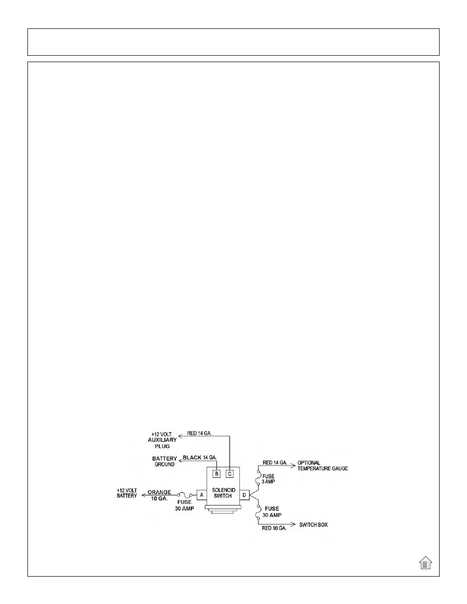
CONTINUOUS DUTY SOLENOID SWITCH
Mount the solenoid switch, drill holes to match if necessary, in a dry and well protected area.
Secure as shown in the parts section with provided 3/8” x 1” capscrews, lockwashers, and hex nuts.
Route wires to and from the Continuous Duty Solenoid Switch as shown below.
A.) ORANGE 10 GA. wire from terminal (A) to +12V battery fusible link.
B.) RED 14 GA. wire from terminal (C) to tractor plug in cab.
C.) BLACK 14 GA. wire from terminal (B) to -12V battery post.
D.) RED 10 GA. wire from terminal (D) to switch box.
E.) RED 14 GA. wire from terminal (D) to temperature gauge. (optional).
(ASM-NH-0032)