Introduction, Port 1, 2, and 3 connectors, Introduction port 1, 2, and 3 connectors – Trimble Outdoors R7 User Manual
Page 104: Tr imble r7 operation
1 0 Cables and Connectors
9 2 Trimble R7/R8 GPS Receiver User Guide
Tr
imble R7 Operation
10.1
Introduction
This chapter provides pinout information for the Trimble R7 receiver
standard and optional cables. This information can be used to build
special cables for connecting the Trimble R7 to devices and
instruments not supported by the standard and optional cables.
10.2
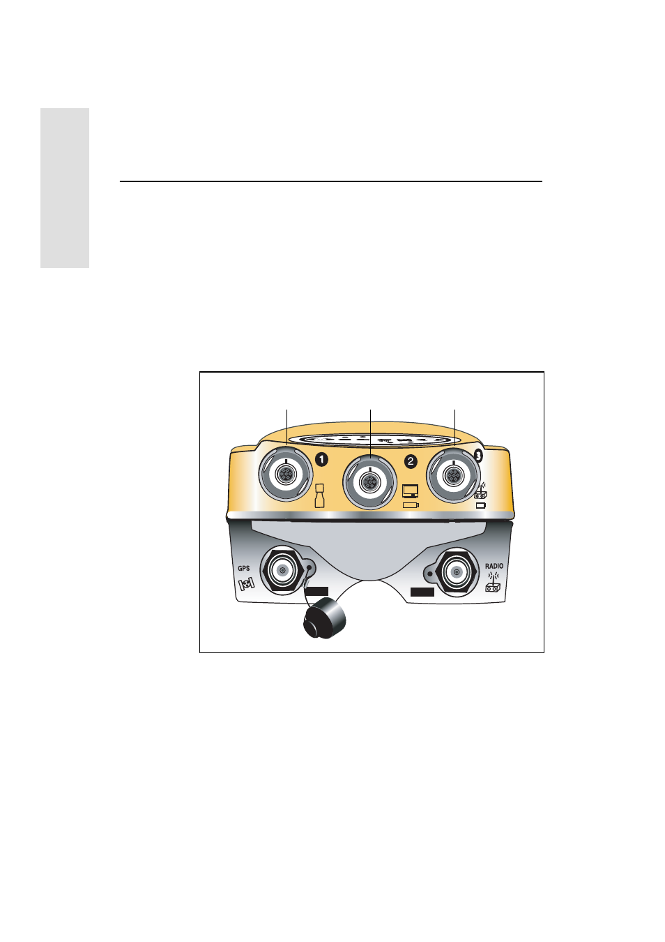
Port 1, 2, and 3 Connectors
Figure 10.1 shows the location of the Trimble R7 serial ports.
Figure 10.1
Trimble R7 serial ports
Port 1
Port 2
Port 3
This manual is related to the following products: