Installation, Dura-flue horizontal installations – Regency FIREGENIE FG39-NG User Manual
Page 13
Regency FG39 FireGenie Freestanding Gas Stove
13
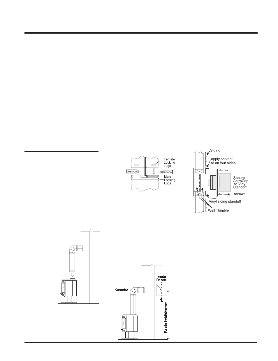
Diagram 5
Note: If installing termination on a siding cov-
ered wall, a vinyl siding standoff or furring
strips must be used to ensure that the
termination is not recessed into the siding.
The four wood screws provided should be
replaced with appropriate fasteners for
stucco, brick, concrete, or other types of
sidings.
5) Before connecting the horizontal run of flue
pipe to the flue termination, slide the black
decorative wall thimble cover over the flue
pipe, then slide the Wall Thimble (Part # 942)
over the flue pipe.
6) Slide the appliance and flue assembly to-
wards the wall carefully inserting the flue
pipe into the flue cap assembly. It is impor-
tant that the flue pipe extends into the flue
cap a sufficient distance so as to result in
a minimum pipe overlap of 1-1/4 inches
(32mm) . Secure the connection between
the flue pipe and the flue cap using sheet
metal screws provided. See diagram 6.
FG39: 59-3/4" (1518mm)
Diagram 2
b) The location of the horizontal flue ter-
mination on an exterior wall must meet
all local and national building codes,
and must not be blocked or obstructed.
For External Flue Termination Loca-
tions, see diagram on page 8.
4) If installing the flue termination to a wall with
vinyl siding, the Vinyl Siding Standoff must
be used. Attach the Vinyl Siding Standoff
to the Horizontal Flue Termination, but first
run a bead of non-hardening mastic around
its outside edges, so as to make a seal
between flue cap and the standoff. Install
the Vinyl Siding Standoff (Part # 950) be-
tween the flue cap and the exterior wall
and attach with the four wood screws
provided. Seal around the Vinyl Siding
Standoff on all four sides. Diagram 5. The
arrow on the flue cap should be point-
ing up. Insure that the 1-1/4" (32mm)
clearances to combustible materials are
maintained. See diagram 5.
line of the horizontal pipe, as shown in
diagram 2. Cut and frame the 10 inch (254mm)
square hole in the exterior wall where the
flue will be terminated. If the wall being
penetrated is constructed of non-combus-
tible material, i.e. masonry block or con-
crete, a 7" (178mm) diameter hole is accept-
able.
Note:
a)
The horizontal run of flue should have
a 1/4 inch (6mm) rise for every 1 foot
(.3m) of run towards the termination.
Never allow the flue to run downward.
This could cause high temperatures
and may present the possibility of a fire.
INSTALLATION
DURA-FLUE
HORIZONTAL
INSTALLATIONS
1) Set the unit in its desired location. Check to
determine if wall studs or roof rafters are
in the way when the fluing system is
attached. If this is the case, you may want
to adjust the location of the unit.
2) Room Sealed pipe and fittings are designed
with special twist-lock connections to con-
nect the fluing system to the appliance flue
outlet. A twist-lock appliance adaptor is
installed on the unit at the fac-
tory. Assemble the desired
combination of pipe and el-
bows to the appliance
adaptor with pipe
seams oriented to-
wards the wall or ceil-
ing, as much out of
view as possible. The
final positioning of the
pipe and 90
o
elbow as-
sembly is deter-
mined by the
mounting orien-
tation of the
adaptor on the
stove and twist-
locked for a sol-
id connection.
Note:
a) Twist-lock procedure: Four indenta-
tions, located on the female ends of
pipes and fittings, are designed to slide
straight onto the male ends of adjacent
pipes and fittings, by orienting the four
Diagram 1
945BG
45
O
Elbow-Swivel-Black
990
90
O
Elbow Galv.
990B
90
O
Elbow-Black
990G
90
O
Elbow-Swivel Galv.
990BG
90
O
Elbow-Swivel-Black
991
High Wind Term. Cap (Vertical)
980
Vertical Term. Cap
982
Snorkel-14" Rise Term.Cap
981
Snorkel-36" Rise Term.Cap
940
Wall Thimble-Support/Box
941
Cathedral/Ceiling-Support/Box
3951
Brass Trim-Wall Thimble/
Ceiling Support
963
Firestop Spacer
943
Flashing 0/12-6/12
943S
Flashing 7/12-12/12
953
Storm Collar
950
Vinyl Siding Standoff
988
Wall Strap
942
Wall Thimble
Parts not supplied by Dura-Flue
946-506/P Flue Guard (Optional)
948-128
Vinyl Siding Shield
Astro Cap (Australian)
pipe indentations so they match and
slide in to the four entry slots on the male
ends (diagram 1). Push the pipe sec-
tions completely together, then twist-
lock one section clockwise approxi-
mately one-quarter turn, until the two
sections are fully locked. The female
locking lugs will not be visible from the
outside on the Black Pipe or fittings.
They may be located by examining the
inside of the female ends. Apply sealant
"Mill-Pac" to inner pipe and high temp
silicone sealant to outer pipe on every
twist-lock joint.
Hint: Apply silicone to female end.
b) Horizontal runs of flue must be support-
ed every three feet. Wall straps are
available for this purpose.
3) With the pipe attached to the stove, slide the
stove into its correct location, and mark the
wall for a 10" x 10" / 254mm x 254mm (inside
dimensions) square hole. The center of the
square hole should line up with the center-