3 switch and led functions, Operational specifications – Renesas SuperH M3A-HS86 User Manual
Page 56
Operational Specifications
3.2.3 Switch and LED Functions
Rev.1.0 Feb 6, 2007
3-20
REJ10J0916-0100
3
3.2.3 Switch and LED Functions
The M3A-HS86 includes six switches and nine LEDs. The MRES switch can be mounted as the option. However,
MRES
_____________
pin is multiplexed with ASEBRKAK
_____________________
/ASEBRK
________________
pin, so do not mount the switch MRES when H-UDI
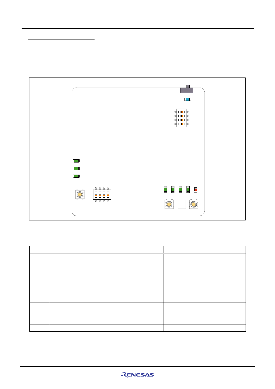
connectors (J1, J2) are used. Figure3.2.4 shows the switch and LED pin layout on M3A-HS86 board. Table3.2.3
lists switches mounted on M3A-HS86.
SW1
LED1
ON
OFF
FLWP
MD0
MD1
FWE
SW4
LED6
PE16
PE17
PE18
LED7
LED8
RESET
SW2
1
2
3
4
ON
SW3
PB6
PB7
PB8
PB9
NMI
MRES
IRQ1
SW5
SW7
SW6
PE
1
PE
2
PE
7
PE
14
LED
9
ON
LED2
LED3
LED4
LED5
Figure3.2.4 Switch and LED Pin Assignment on M3A-HS86 Board
Table3.2.3 Switches Mounted on M3A-HS86
No. Function
Remarks
SW1
System power on/off switch
-
SW2
System reset input switch
See section 2.8 for details.
SW3
DIP switch open to the user (4-pole)
SW3-1 OFF : PB6=H, ON : PB6=L
SW3-2 OFF : PB7=H, ON : PB7=L
SW3-3 OFF : PB8=H, ON : PB8=L
SW3-4 OFF : PB9=H, ON : PB9=L
PB6, PB7, PB8 and PB9 are pulled up.
See section 2.5 on chapter 2 for details.
SW4
System setup DIP switch (4-pole)
See Table3.2.4 for the functions
SW5
NMI input switch
See section 2.9 of chapter 2 for details.
SW6
IRQ1 input switch
See section 2.9 of chapter 2 for details.
SW7 MRES
*
input switch
Not mounted.
*: By MRES (manual reset), each register of the on-chip peripheral module is not initialized though an internal state of
CPU is initialized.