6 extension connectors (j9-j13) – Renesas SuperH M3A-HS86 User Manual
Page 46
Operational Specifications
3.1.6 Extension Connectors (J9-J13)
Rev.1.0 Feb 6, 2007
3-10
REJ10J0916-0100
3
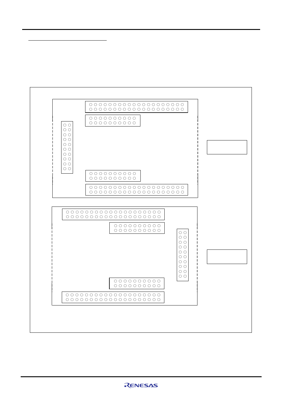
3.1.6 Extension Connectors (J9-J13)
The M3A-HS86 includes extension connectors to which the I/O pins of the SH7086 are connected.
MIL standard connectors can be connected to J9-J13, allowing the user to create extension board or monitor the
SH7086 bus signals.
Figure3.1.8 shows a pin assignment of extension connector.
Board
Edge
19
20
1
2
J11
40
39
2
1
20
19
2
1
Top View of the
Solder Side
J13
J12
40
39
2
1
20
19
2
1
J10
J9
Board
Edge
[Note]:The pin numbers on CPU board are defined based on that extension connectors
are mounted on the component side. Thus, the pin assignments on the extension
connector side and the CPU board side are different when mounting extension
connectors on the solder side.
19
20
1
2
J11
40
39
2
1
20
19
2
1
J13
J12
40
39
2
1
20
19
2
1
J10
J9
Top View of the
Component Side
Board
Edge
Board
Edge
Figure3.1.8 Pin Assignment of Extension Connectors (J9-J13)
- Single-Chip Microcomputer M34551T2-MCU (42 pages)
- M3T-FLX-80NRA (6 pages)
- 70 (162 pages)
- M16C/30P (102 pages)
- PROM Programming Adapter PCA7427G02 (20 pages)
- R0E572110CFK00 (40 pages)
- H8/325 Series (20 pages)
- Single-Chip Microcomputer H8/36079 (27 pages)
- Direct Dummy IC M3T-DIRECT100S (4 pages)
- M3A-2152 (95 pages)
- PCA7755D (6 pages)
- M16C/6N5 (106 pages)
- SH7085 (50 pages)
- QFP-144 (23 pages)
- H8/3834 Series (22 pages)
- RSKM16C62P (3 pages)
- H8/33937 (22 pages)
- Single-Chip Microcomputer H8SX/1622 (5 pages)
- E6000 (29 pages)
- PCA7400 (18 pages)
- PCA4738FF-64 (20 pages)
- SuperH HS7339KCU01HE (43 pages)
- M16C FAMILY (103 pages)
- PCA7412F-100 (20 pages)
- 4513 (210 pages)
- M34551E8FP (16 pages)
- Dummy IC M3T-SSOP36B-450 (4 pages)
- Emulation Pod M30100T3-RPD-E (52 pages)
- Converter Board for M30102 M30102T-PTC (4 pages)
- SH7145 (31 pages)
- HS1653ECN61H (36 pages)
- Converter Board R0E521276CFG00 (4 pages)
- PCA7302E1F-80 (18 pages)
- H8/3814 Series (21 pages)
- H8S/2646 Series (20 pages)
- SuperHTM Family SH7125 Series (40 pages)
- M30262T-PTC (4 pages)
- SH7670 (82 pages)
- H8/3864 Series (20 pages)
- Emulator System M3T-MR100 (306 pages)
- 38K0 (6 pages)
- PLQP0176KB-A (40 pages)
- Direct Dummy IC M3T-DIRECT80S (6 pages)
- PCA4738L-80A (26 pages)
- Converter Board R0E5212BACFG00 (6 pages)