Clearances, Table c: clearances from combustible surfaces, Table d: clearances to protected surfaces – Raypak 1334001 User Manual
Page 8
8
Heater
Model
Number
Floor Base
Part
Number
0133
001749
0182/0181
058313
0260/0261
058314
0330/0331
058315
0400/0401
058316
0514
056199
0624
056200
0724
056201
0824
056202
0926*
054597
1083*
054598
1178*
054599
1287*
054600
1414*
054601
1571*
058378
1758*
058379
0962
059233
1125
059234
1223
059235
1336
059236
1468
059237
1631
059238
1826
059239
*Models with factory installed floor
shield as standard.
BOLD TYPE indicates Low NOx models.
Table B: Combustible Floorshield Ordering Information
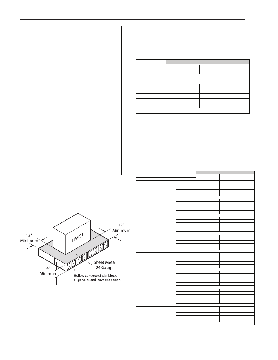
Fig. 2: Alternate Method for Providing a Non-
Combustible Base
Clearances
Installation Clearances
(All Dimensions are in Inches)
0133
0181 to
0514 to 0926 to 2100 to
Location
0401
0824
1826
4001
Floor
Front
Back
12
12
12
24
24
Right
6
12
6
24
24
Left
12
12
18
24
24
*Vent
6
6
6
6
6
Indoor Top
42
39
36
24
24
Outdoor Top
NA
See Note 1
See Note 2
Unobstructed
Heater Size
Table C: Clearances From Combustible Surfaces
Note 1: Combustible floor shield is required when heater is to be
installed on a combustible surface. (See ordering info.)
Note 2: Servicing Clearances: Provide at least 24" (Models 0133-
1826), 48" (Models 2100-4001) in front of unit for removal &
servicing of the Controls & Burner Tray. Provide at least 18" on side
opposite water connections for deliming of Heat Exchanger Tubes.
*Vent includes factory supplied drafthoods and does not include field
supplied vent systems above the drafthood. On Models 2100-4001
drafthood is built into heater.
Heater Size
0133
0181 to 0514 to
0926 to
2100 to
Description
Location
0401
0824
1826
4001
a. 3-1/2 in. thick masonry walls
Back
9
9
9
16
16
without ventilated air space.
Right
5
9
5
16
16
Left
9
9
12
16
16
Vent
5
5
5
5
5
Indoor Top
43
39
36
24
24
Outdoor Top
Unobstructed
NA
b. 1/2 in. insulation board
Back
6
6
6
12
12
over 1 in. glass fiber or
Right
3
6
3
12
12
mineral wool batts.
Left
6
6
9
12
12
Vent
3
3
3
3
3
Indoor Top
30
30
24
16
16
Outdoor Top
Unobstructed
NA
c. 0.024 sheet metal over 1 in.
Back
4
4
4
8
8
glass fiber or mineral wool
Right
3
4
3
8
8
batts reinforced with wire
Left
4
4
6
8
8
on rear face with ventilated
Vent
3
3
3
3
3
air space.
Indoor Top
24
24
18
12
12
Outdoor Top
Unobstructed
NA
d. 3-1/2 in. thick masonry wall
Back
6
6
6
8
8
with ventilated air space.
Right
6
6
6
8
8
Left
6
6
6
8
8
Vent
6
6
6
6
6
Indoor Top
42
39
36
24
24
Outdoor Top
NA
Unobstructed
NA
e. 0.024 sheet metal with
Back
4
4
4
8
8
ventilated air space.
Right
2
4
2
8
8
Left
4
4
6
8
8
Vent
2
2
2
2
2
Indoor Top
24
24
18
12
12
Outdoor Top
Unobstructed
NA
f. 1/2 in. thick insulation
Back
4
4
4
8
8
board with ventilated
Right
3
4
3
8
8
air space.
Left
4
4
6
8
8
Vent
3
3
3
3
3
Indoor Top
24
24
18
12
12
Outdoor Top
NA
Unobstructed
NA
g. 0.024 sheet metal with
Back
4
4
4
8
8
ventilated air space over
Right
3
4
3
8
8
0.024 sheet metal with
Left
4
4
6
8
8
ventilated air space.
Vent
3
3
3
3
3
Indoor Top
24
24
18
12
12
Outdoor Top
Unobstructed
NA
h. 1 in. glass fiber or mineral
Back
4
4
4
8
8
wool batts sandwiched
Right
3
4
3
8
8
between two sheets 0.024
Left
4
4
6
8
8
sheet metal with ventilated
Vent
3
3
3
3
3
air space.
Indoor Top
24
24
18
12
12
Outdoor Top
NA
Unobstructed
NA
Table D: Clearances to Protected Surfaces