Gas pressure regulator, Venting of diaphragm gas components – Raypak 1334001 User Manual
Page 21
21
Gas Pressure Regulator
The gas pressure regulator located in the gas valve is
preset nominally at 4" WC for natural gas, and 11" WC
for propane. Between the gas valve and the burners is
a 1/8" pipe plug. The pressure at this point, taken with
a manometer, should be about 3.7" WC natural gas
and 10.5" WC propane. Models 0181, 0261, 0331, and
0401 should be 3.9 WC natural gas. If an adjustment
is needed, turn adjustment screw clockwise to
increase pressure, or counter-clockwise to decrease
pressure.
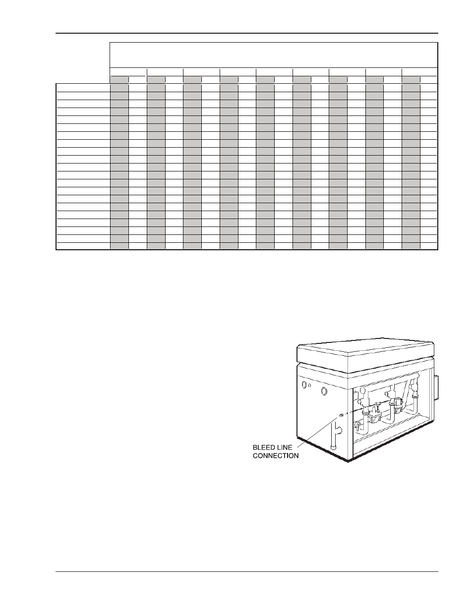
Venting of Diaphragm Gas
Components
Gas train components that have diaphragms in their
construction are supplied with a bleed line connection
that must be connected to the outside atmosphere as
required by the National Fuel Gas Code. Under NO
circumstances shall bleed lines terminate in the gas
utilization equipment flue or exhaust system.
Fig. 20: Bleed Line Connection
N
P
N
P
N
P
N
P
N
P
N
P
N
P
N
P
N
P
0133
15
35
60
145
200
500
*0182/0181
-
15
30
65
95
250
400
-
-
-
-
-
-
-
-
-
-
-
*0260/0261
-
10
20
40
60
140
250
560
-
-
-
-
-
-
-
-
-
*0330/0331
-
15
25
35
85
150
380
360
-
-
-
-
-
-
-
-
-
*0400/0401
-
-
15
25
60
100
260
250
-
-
-
-
-
-
-
-
-
0
0
5
0
6
3
0
3
1
0
5
1
5
6
5
3
5
1
0
1
-
4
1
5
0
-
-
-
-
-
-
-
0
4
3
0
5
2
5
9
0
0
1
5
4
5
2
0
1
-
-
4
2
6
0
-
-
-
-
-
-
-
0
0
6
0
6
2
0
8
1
5
7
0
8
5
3
0
2
-
-
-
4
2
7
0
-
-
-
-
-
-
0
0
5
0
8
4
5
8
1
0
3
1
5
5
0
6
5
2
5
1
-
-
-
4
2
8
0
-
-
-
-
-
0926/0962
-
-
-
15
20
45
45
110
150
360
400
-
-
-
-
-
1083/1125
-
-
-
10
15
35
35
80
120
300
300
-
-
-
-
-
1178/1223
-
-
-
-
-
25
25
60
85
220
200
-
-
-
-
-
1287/1336
-
-
-
-
-
25
20
55
75
180
170
325
560
-
-
-
1414/1468
-
-
-
-
-
20
15
45
65
150
165
300
500
-
-
-
1571/1631
-
-
-
-
-
15
15
35
50
120
125
250
400
-
-
-
1758/1826
-
-
-
-
-
15
10
30
40
100
100
225
340
-
-
-
2100
-
-
-
-
-
10
10
25
30
80
75
175
260
-
-
-
2500
-
-
-
-
-
-
-
15
20
55
55
135
160
400
600
-
3001
-
-
-
-
-
-
-
10
15
35
40
85
120
250
500
-
3500
-
-
-
-
-
-
-
-
10
30
30
45
80
200
400
600
4001
-
-
-
-
-
-
-
-
5
20
25
35
65
160
300
400
1-1/2"
3/4"
MAXIMUM EQUIVALENT PIPE LENGTH
NATURAL GAS 1000 BTU/Cubic Foot .60 SPECIFIC GRAVITY @ 0.5" W.C. PRESSURE DROP
2"
2-1/2"
3"
4"
PROPANE GAS 2500 BTU/Cubic Foot 1.53 SPECIFIC GRAVITY @ 0.6" W.C. PRESSURE DROP
"
4
/
1
-
1
"
1
"
2
/
1
* Models 0181, 0261, 0331, and 0401 are Low NOx units and are not available in propane.
A minimum of 7" WC and a maximum of 10.5" WC upstream pressure under load, and no load conditions must be provided for natural gas
or a minimum of 11" WC and a maximum of 13" for propane.
Pressure drops from the no load condition to the full load condition must be no more than 30% for proper operation.
Table G: Maximum Equivalent Pipe Lengths