Burner adjustment, Visual inspection, Electrical – Raypak 1334001 User Manual
Page 34: High gas pressure switch, Burner tray removal, Gas valve removal
34
c. Check the ignition spark operation. Time must
be within the lockout timing period (15 or 90 sec-
onds).
d. Turn control down to end call for heat and wait
60 seconds on lockout models before beginning
step 3.
3. Turn on gas supply.
4. Set controller to call for heat.
5. System should start as follows:
a. Spark will turn on and pilot gas valve will open
and the blower will begin running.
b. Heater will operate until call for heat is satisfied.
burner Adjustment
This burner assembly does not require any primary air
adjustments.
Visual Inspection
Flame can be observed through the slot opening
above the plenum. Flame color is blue and evenly
spread on the top surface of the burner. A visual
inspection should be made monthly of the burners. In
case flame lifting is observed on the burner, check gas
pressure on manifold and static pressure in plenum.
Gas pressure in manifold should be 3.9" WC and stat-
ic pressure in plenum should be greater than 0.5" WC.
Electrical
Be sure that electrical service to the heater has prop-
er overload fuse or circuit breaker protection, and wire
size and connections comply with all applicable codes.
High Gas Pressure Switch
Pressure switch senses high pressure and automati-
cally shuts down burner if abnormal pressure exists.
Fig. 34: Gas Pressure Switch
burner Tray Removal
1. Shut-off main electrical power switch to heater.
2. Shut-off gas upstream of heater.
3. Remove front door.
4. Disconnect gas line from gas valve.
5. Remove (2) screws that mount burner tray to unit,
and (4) screws that secure gas valve to jacket.
6. Disconnect wires that terminate at gas valve.
7. Unscrew (4) screws that secure the control box.
8. Disconnect pilot wire from the ignition module.
9. Disconnect wire harness from the combustion
blower.
10. Carefully slide out the burner tray assembly.
11. Reverse above procedure to reinstall.
Gas Valve Removal
1. Shut-off main electrical power switch to heater.
2. Shut-off gas supply to the heater.
3. Remove front door.
4. Disconnect gas line from gas valve.
5. Disconnect wires, pilot tubing and bleed line, if
required.
6. Remove (2) screws that secure gas valve to jack-
et.
7. Turn vertical gas pipe from manifold slightly and
unscrew gas valve.
8. Reverse above procedure to re-install.
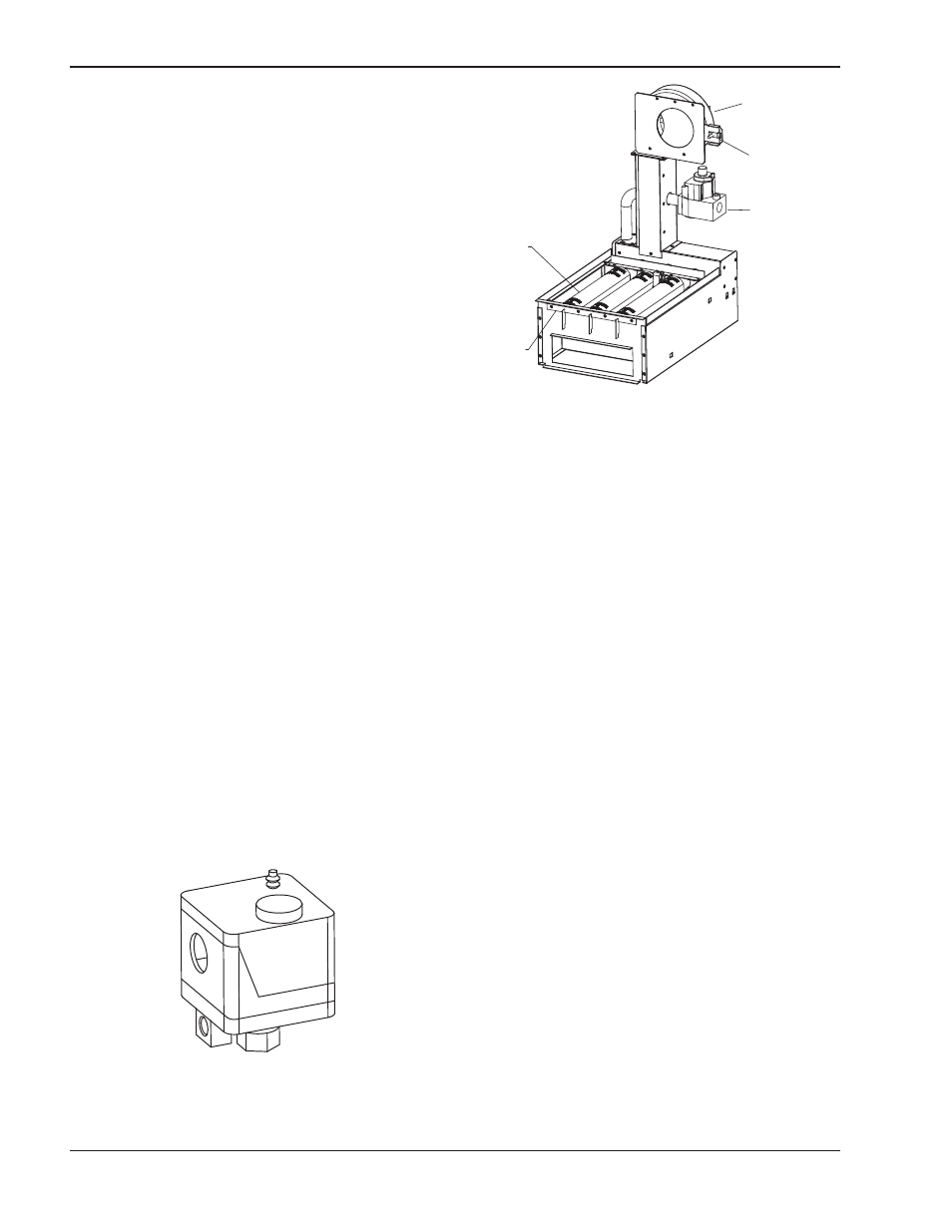
BURNER
BURNER
HOLD-
DOWN
BRACKET
GAS
VALVE
COMBUSTION
AIR BLOWER
AIR SHUTTER
ADJUSTMENT
Fig. 35: Low NOx Burner Tray Assembly