Vent damper, Damper open damper closed – Raypak 1334001 User Manual
Page 19
19
NO
YES
NO
YES
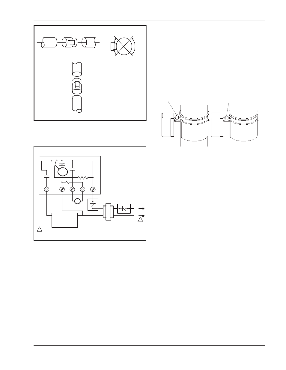
INSTALL VENT
DAMPER WITH
ACTUATOR TO
SIDES OF VENT
ONLY. DO NOT
MOUNT ABOVE OR
BELOW VENT.
TO CHIMNEY
TO BOILER
D808
FLOW >
HORIZONTAL INSTALLATION
TO CHIMNEY
TO BOILER
D808
VERTICAL
INSTALLATION
ACTUATOR MAY BE
INSTALLED IN ANY
POSITION ON
VERTICAL PIPE.
HEATER
HEATER
Motor
End
Switch
C.
N.O.
N.C.
1K2
1K1
R
1R
1K3
1
2
3
4
5
D808
Thermostat or
Controller
Dual Valve
Combination Gas
Control or
Ignition System
Optional Limit
Location
Limit
Transformer
L1
(Hot)
L2
1
1
Yellow Blue
Power supply provide disconnect me
ans an overload protection as requ
ired.
Black Orange Red
Power supply provide disconnect means an overload protection as required.
Fig. 16: Installing Vent Damper
Fig. 17: Vent Damper General Wiring Diagram
INSTALL THE VENT DAMPER TO SERVICE ONLY
THE SINGLE APPLIANCE FOR WHICH IT IS
INTENDED. IF IMPROPERLY INSTALLED, A HAZ-
ARDOUS CONDITION, SUCH AS AN EXPLOSION
OR CARBON MONOXIDE POISONING, COULD
RESULT.
Vent Damper
For safe, efficient operation, the vent damper and all
flue product carrying areas of the appliance must be
checked annually, with particular attention given to
deterioration from corrosion or other sources. Check
vent damper operation as follows:
1. When the heater is off, check that the vent damper
position indicator points to the closed position, Fig.
18.
2. Turn the thermostat or controller up to call for heat
and check that the vent damper indicator points to
the open position, Fig. 18.
3. Turn the thermostat or controller down again and
check that the vent damper position indicator
returns to the closed position.
THE VENT DAMPER MUST BE INSPECTED AT
LEAST ONCE A YEAR BY A TRAINED, EXPERI-
ENCED SERVICE TECHNICIAN. THE NAME OF THE
PERSON WHO ORIGINALLY INSTALLED YOUR
VENT DAMPER IS SHOWN ON THE INSTALLATION
LABEL. DAMPER MUST BE IN THE OPEN POSI-
TION WHEN HEATER MAIN BURNERS ARE
OPERATING.
Damper
Position
Indicator
DAMPER OPEN DAMPER CLOSED
Damper
Position
Indicator
Fig. 18: Vent Damper position Indicator Showing Open
& Closed Positions