Electrical connections, 100% pilot safety, Low water cut-off (optional) – Raypak 1334001 User Manual
Page 27: High and low gas pressure switches (optional)
27
100% Pilot Safety
Models 0514-4001 employ electronic devices which
close the main gas valve within 8/10 of a second
whenever the pilot flame is interrupted. Pilot flame is
automatically lit when the device is powered. Unit per-
forms its own safety check and opens the main valve
only after the pilot is proven to be lit.
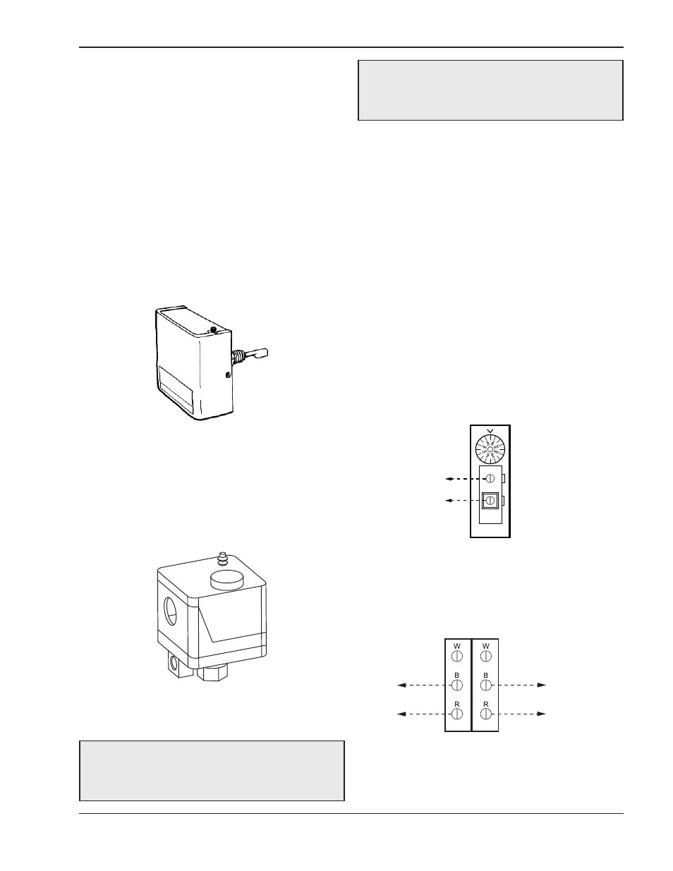
Low Water Cut-Off (Optional)
The low water cut-off automatically shuts down burner
whenever water level drops below probe. 5-second
(max) time delay prevents premature lockout due to
temporary conditions such as power failure or air
pockets. Flush float type devices at beginning of each
heating season.
High and Low Gas Pressure
Switches (Optional)
These switches sense either high or low gas pres-
sures and automatically shut down burners if abnormal
pressures exist.
Electrical Connections
Fig. 27: Low Water Cut-Off
Fig. 28: Gas Pressure Switch
The heater is normally wired for 120 Volts. The voltage
is indicated on the tie-in leads. Consult the wiring dia-
gram shipped with the heater in the instruction packet.
The "TH" leads are for the remote tank control connec-
tion. 24 Volts are supplied to this connection through
the heater transformer. DO NOT attach line voltage to
the "TH" leads on models 0514-1826. Before starting
heater check to ensure proper voltage to heater and
pump.
Heater must be electrically grounded in accordance
with National Electrical Code ANSI/NFPA No 70.
NOTES:
1. Field install ground wire to inside of junction box.
2. If any of the original wire supplied with the heater
must be replaced, it must be replaced with 105°C wire
or its equivalent.
CAUTION: Label all wires prior to disconnection
when servicing controls. Wiring errors can cause
improper and dangerous operation. Verify proper
operation after servicing.
DANGER - SHOCK HAZARD: Make sure
electrical power to the heater is disconnected to
avoid potential serious injury or damage to
components.
SINGLE
STAGE
TANKSTAT
STAGE 1
CONNECTION
ATTACH STAGE 1 CONNECTIONS
ON HEATER TO THE SINGLE STAGE
TANKSTAT AS SHOWN IN THE DIAGRAM ABOVE.
2-STAGE
TANKSTAT
STAGE 1
CONNECTION
STAGE 2 CONNECTION OR
STAGE 1 CONNECTION
OF HEATER 2
ATTACH STAGE 1 CONNECTIONS ON HEATER
TO STAGE 1 CONNECTION ON TANKSTAT.
ATTACH STAGE 2 CONNECTIONS OR
STAGE 1 CONNECTION OF HEATER 2
TO STAGE 2 CONNECTION ON TANKSTAT
AS SHOWN IN THE DIAGRAM.
Fig. 29: Single-Stage Tankstat
Fig. 30: 2-Stage Tankstat (2 On/Off Units)