Installation, Option 1: remote control, Option 2: wall switch – Regency P121 User Manual
Page 32: Option 3: wall thermostat
Regency
®
P121-2/P121LC-2/P121RC-2/P131-2 Zero Clearance Direct Vent Gas Fireplace
32
Option 1:
REMOTE CONTROL
Can be used with Option 2 or 3
but not both.
Use the Regency
®
Remote Control Kit approved
for this unit. Use of other systems may void
your warranty.
The remote control kit comes with a hand held
transmitter, a receiver and a wall mounting
plate.
1) Choose a convenient location on the wall
to install the receiver and the receptacle
box (protection from extreme heat is very
important). Run wires from the fi replace
to that location. Use the Thermostat Wire
Table.
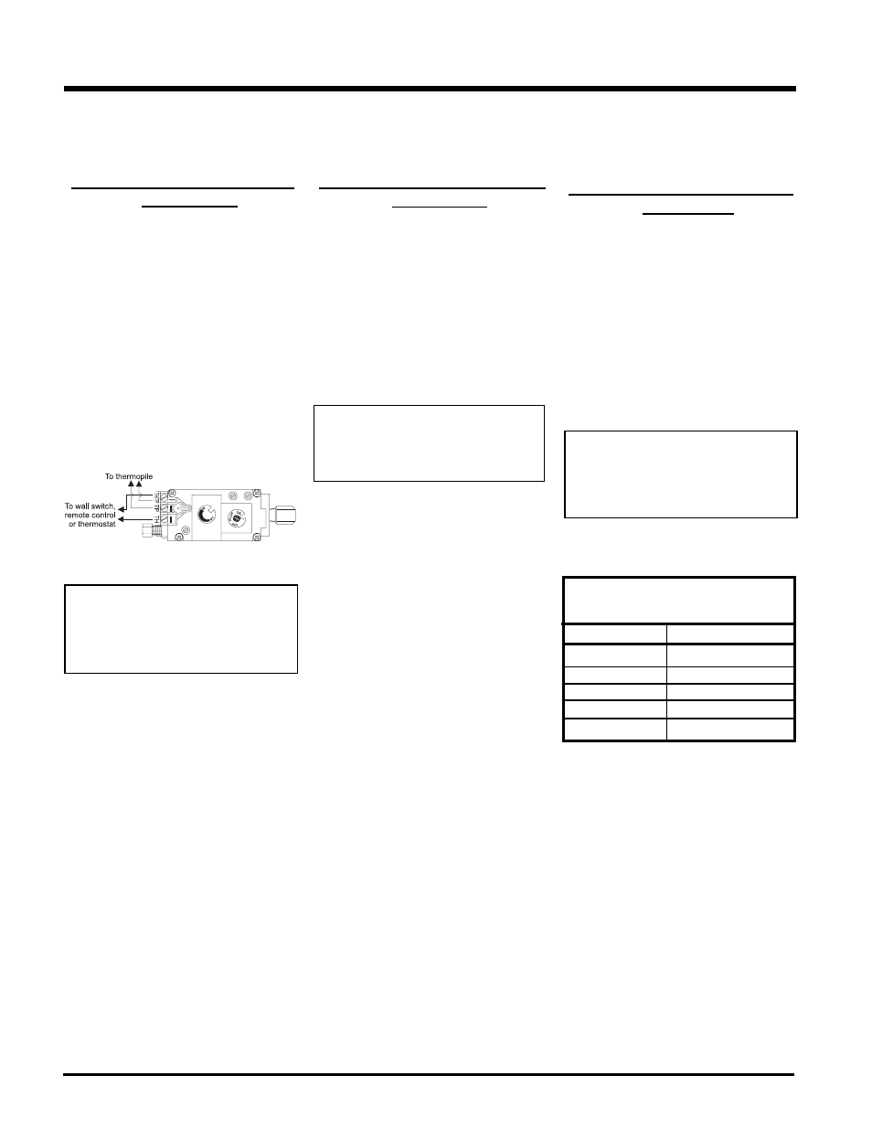
2) Connect the two wires to the gas valve. See
diagram below.
Option 2:
WALL SWITCH
Can be used with Option 1 or 3
but not both.
1) Run the supplied 15' of wire through the back
gas inlet opening. Be careful not to damage
wire.
Note: We recommend a maximum of 15'
of wire but if you wish to go with a
longer run, use the Thermostat Wire
Table.
2) Connect the wire to the supplied wall switch
and install into the receptacle box.
Thermostat Wire Table
Option 3:
WALL THERMOSTAT
Can be used with Option 1 or 2
but not both.
A wall thermostat may be installed if desired,
connect the wires as per the wiring diagram.
Use the table below to determine the maximum
wire length.
Note: Preferable if the thermostat is installed
on an interior wall.
Regency
®
offers an optional programmable
thermostat but any 250-750 millivolt rated non-
anticipator type thermostat that is CSA, ULC or
UL approved may be used.
3) Install 3 AAA alkaline batteries in transmitter
and 4 AA alkaline batteries in the receiver.
Install the receiver and its cover in the wall.
Switch the remote receiver to "remote"
mode. The remote control is now ready for
operation.
INSTALLATION
CAUTION
Do not connect millivolt
remote control wires to a
120V wire.
CAUTION
Do not connect millivolt all
switch wire to a 120V wire.
CAUTION
Do not connect millivolt
wall thermostat wires
to a 120V wire.
14 GA.
16 GA.
18 GA.
20 GA.
22 GA.
50 Ft.
32 Ft.
20 Ft.
12 Ft.
9 Ft.
Recommended Maximum Lead Length
(Two-Wire) When Using Wall
Thermostat (CP-2 System)
Wire Size Max. Length