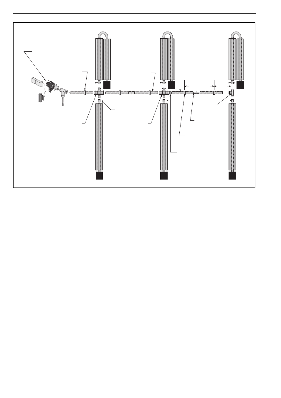
Figure 25: typical manifold layout, Linear and u-tube configuration) – Roberts-Gordon HE15UT User Manual
Page 42
B
LACKHEAT
®
HE I
NSTALLATION
O
PERATION
AND
S
ERVICE
M
ANUAL
36 of 73
Figure 25: Typical Manifold Layout (Linear and U-Tube Configuration)
*Typical Fan
Arrangement
150 mm Hanger
150 mm Manifold
Damper (Typical)
Cross
(100 x 150 x 100 x 150)
100 mm Manifold
100 mm Hanger
ID/ID Sleeve
Tee
(100 x 100 x 100)
Cross
(100 x 150 x 100 x 150)
Max
3000 mm
HE25ST
HE25UT
HE25ST
HE25UT
HE25ST
HE25UT
NOTE: Be sure to
silicone seal all
manifold joints.
Reducer
(100 x 150)
Max
1000
mm
*Locate fan
away from wet
environment.