Operational specifications – Renesas M3A-HS60 User Manual
Page 46
Operational Specifications
3.2.2 Switch and LED Functions
Rev.1.00 June 1,2005
3-16
REJ11J0002-0100Z
3
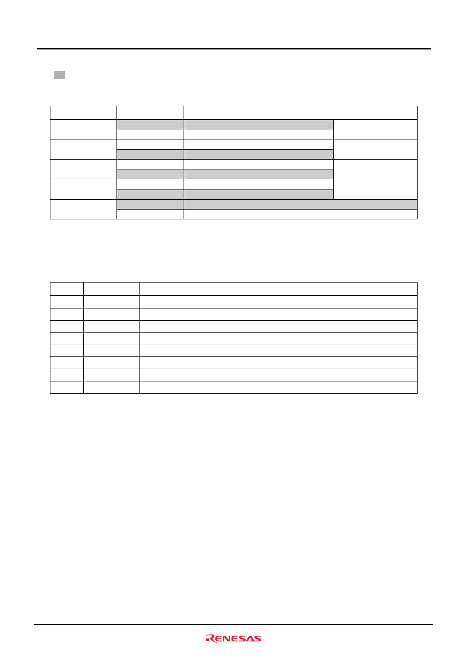
Table3.2.4 lists the functions of the switch SW4.
: Initial Setting
Table3.2.4 Functions of the Switch SW4
No. Setting
Function
OFF
SDRAM_SZ=H (32-bit access)
SW4-1
*
SDRAM_SZ
ON
SDRAM_SZ=L (16-bit access)
Sets SDRAM bus width
OFF
MD_CLK2 pin state “H” (Disable setting)
SW4-2
MD_CLK2
ON
MD_CLK2 pin state “L” (clock mode 2)
Sets clock mode
OFF Disable
setting
SW4-3
Reserved
ON
This setting should always be "ON"
OFF Disable
setting
SW4-4
Reserved
ON
This setting should always be "ON"
Reserved
(Disable setting)
OFF
Releases write protect for the flash memory(WP0# pin state “H”)
SW4-5
FLASH _WP#
ON
Write protects the flash memory(WP0# pin state “L”)
*
When using the J6 connector, make sure the SDRAM bus width is set to 16-bit access (SW4-1 OFF).
Table3.2.5 lists the functions of the LEDs mounted in M3A-HS60.
Table3.2.5 Functions of the LEDs Mounted in M3A-HS60
No. Color
Functions/Remarks
LED1 Red
Power-on LED (LED1 lights when 3.3 V power is supplied)
LED2 Green
Open to the user (LED2 lights when PE1 outputs
"
L
"
)
LED3 Green
Open to the user (LED3 lights when PE2 outputs
"
L
"
)
LED4 Green
Open to the user (LED4 lights when PE8 outputs
"L"
)
LED5 Green
Open to the user (LED5 lights when PE10 outputs
"L"
)
LED6 Green
Open to the user (LED6 lights when PE11 outputs
"L"
)
LED7 Green
Open to the user (LED7 lights when PE14 outputs
"L"
)
LED8 Green
Open to the user (LED8 lights when PE15 outputs
"L"
)