7 clock module, Functional overview – Renesas M3A-HS60 User Manual
Page 27
Functional Overview
2.7 Clock Module
Rev.1.00 June 1,2005
2-13
REJ11J0002-0100Z
2
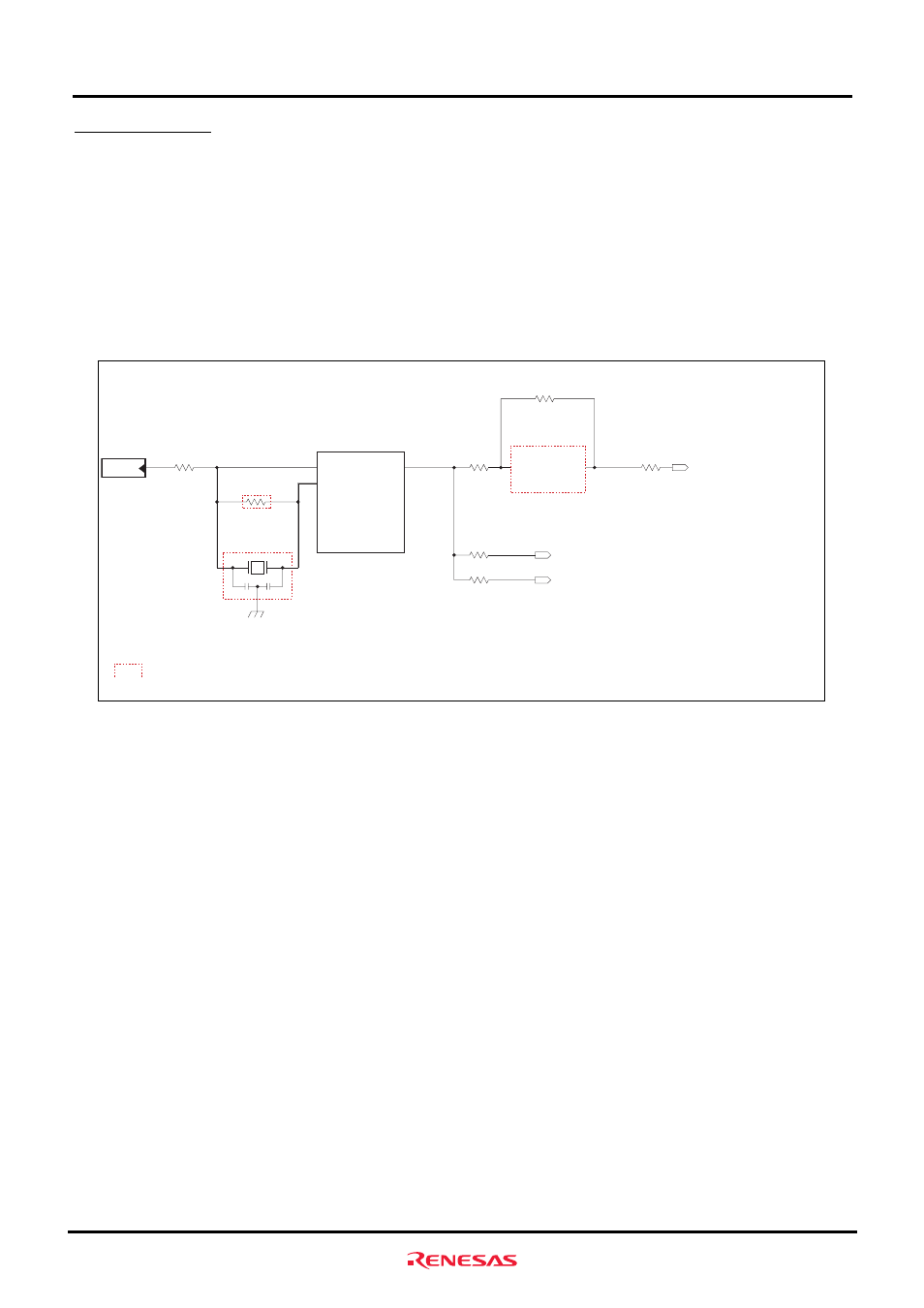
2.7 Clock Module
The clock module in the M3A-HS60 consists of the following two blocks:
• Output from a oscillator connected to EXTAL of the SH7206
• Ceramic resonator connected to EXTAL and XTAL
The M3A-HS60 has a 16.67MHz oscillator connected. Furthermore, the bus clock output from the SH7206 is connected
to the SDRAM via a damping resistor. To connect an extension board to the extension connector, we recommend
including a clock buffer that contains a PLL to ensure that the board will be supplied with a stable clock signal.
Figure2.7.1 shows a block diagram of clock module.
EXTAL
XTAL
CKIO
SH7206
CSTCE-G16M67(Murata)
CY2305SC-1H(Cypress)
CLK
:Not mounted parts
Clock Buffer
*2:To mount a clock buffer, remove the resistor 14
R14
*1:To mount ceramic resonator, remove the resistor 18
*2
*1
R18
R82
Ceramic
Resonator
EXCLK(Extension connector)
CLKIH(SDRAM upper bytes)
CLKIL(SDRAM lower bytes)
Oscillator
Not mounted
Not mounted
Figure2.7.1 Block Diagram of Clock Module