Roberts Gorden Combat Cabinet Heaters POP-ECA/PGP-ECA 015 to 0100 User Manual
Page 42
COMBAT
®
C
ABINET
H
EATERS
I
NSTALLATION
, C
OMMISSIONING
, O
PERATION
AND
S
ERVICE
M
ANUAL
36
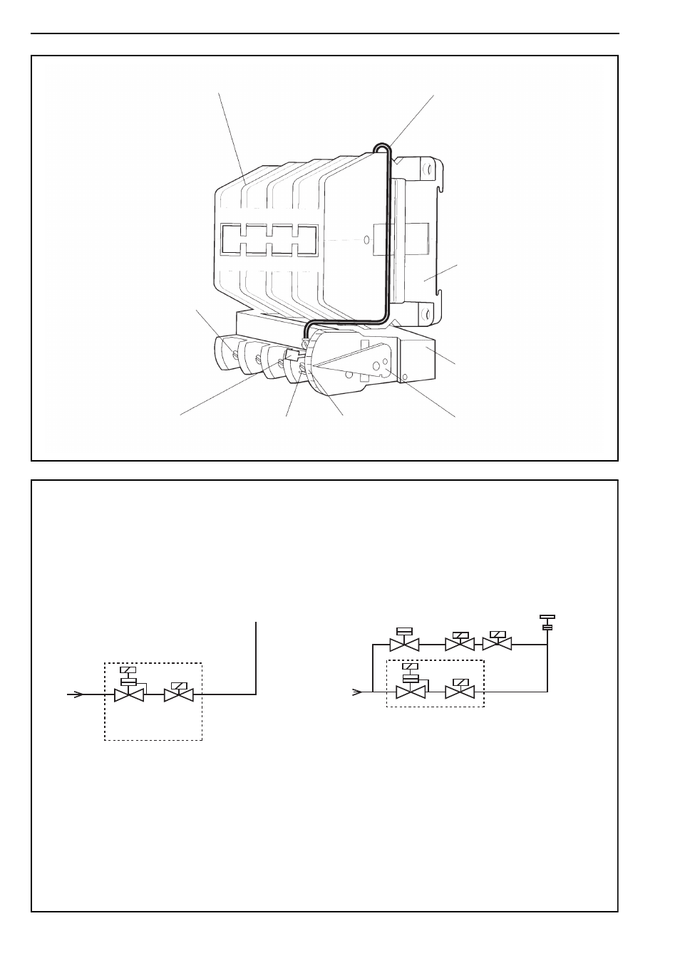
Figure 15: Motor Starter (models 040 -100 and Thermal Overload (models 060 - 100)
Figure 16: Gas Train Circuit for Dungs Gas Valves (all models)
Line Connections
Load Connections
Contactor
Thermal
Overload
Overload
Reset Button
Overload
Connection
Overload Scale
(motor current amps)
Overload
Adjusting Level
Wire Connecting
Overload Switch to Coil
Models 15 to 30 - All types of valve
Models 40 to 100 - All types of valve
To Burner
To Burner
Burner
Flange
Union
Automatic
Gas Valve &
Regulator
Automatic
Gas Valve &
Regulator
Gas
Inlet
Gas
Inlet
Automatic
Gas Valve
Automatic
Gas Valve
Automatic
Gas Valves
1 = Start Gas
2 = Main Gas
TP1
TP1
1
1
1
1
T
T
T
2
2
TP2
TP2
TP3
TP3
TP1 = Inlet Pressure
TP2 = Pressure between Main Gas Valves
TP3 = Valve Outlet Pressure
Burner Pressure TP on Burner
NOTE: Orifice plate
fitted into union
between valve and
burner where required.
NOTE: Orifice plate
fitted into union
between valve and
burner for models
40/50, and burner flange
for models 60 and over.
Regulator