Roberts Gorden Combat Cabinet Heaters POP-ECA/PGP-ECA 015 to 0100 User Manual
Page 34
COMBAT
®
C
ABINET
H
EATERS
I
NSTALLATION
, C
OMMISSIONING
, O
PERATION
AND
S
ERVICE
M
ANUAL
28
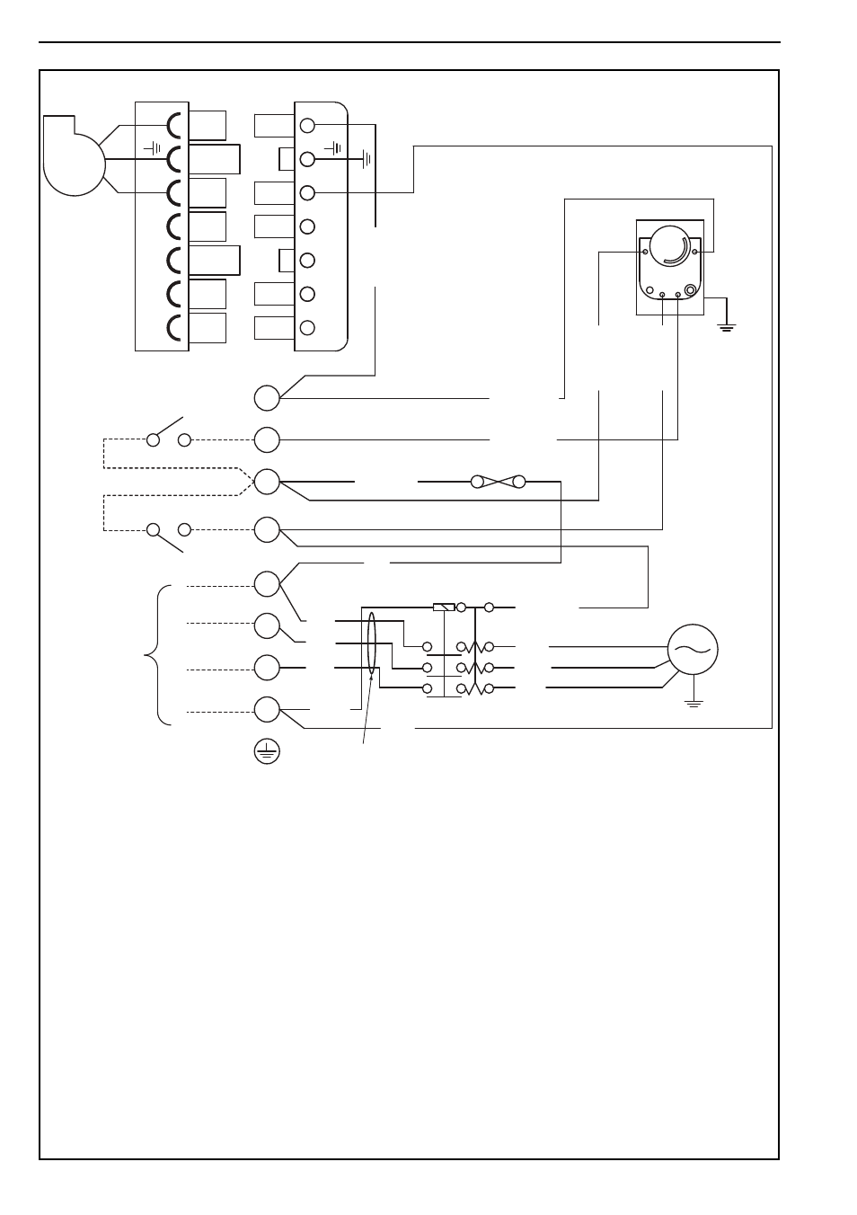
9.11 CCH Wiring Diagram Gas Models 60-100 (floor standing)
1
2
3
10 A
TIME/TEMPERATURE
CONTROLS
FAN CONTROL
L 1
FAN
LIMIT
FAN / LIMIT STAT
4
PACKAGED
BURNER
Red
N
MAIN
FAN
MOTOR
MAIN TERMINALS
IN CONTROL PANEL
Red
Grey
Black
Brown
CONTACTOR
400 V 50 Hz
3 PH SUPPLY
Blue
Blue
Red
Red
L
L
2
3
R1
1 mm2 Ø RED TRI RATED FLEX CABLE
Red / White
Red / White
Red / White
Red / White
R
ed /
W
hit
e
R
ed /
W
hit
e
R
ed /
W
hit
e
B4
S3
T2
T1
N
L1
B4
S3
T2
T1
N
L1
GAS BURNER 7-WAY PLUG
NOTE:
Any of the original wire supplied with the
heater must be replaced with wiring material
having a temperature rating of at least 105°C
and 600 V.