Roberts Gorden Combat Cabinet Heaters POP-ECA/PGP-ECA 015 to 0100 User Manual
Page 26
COMBAT
®
C
ABINET
H
EATERS
I
NSTALLATION
, C
OMMISSIONING
, O
PERATION
AND
S
ERVICE
M
ANUAL
20
2. The control will then adjust the burner input
continuously to attempt to maintain the
temperature set on the control.
3. If the temperature continues to rise with the
burner operating at minimum fire, the control
will turn off the burner until the temperature falls
again, and the burner will restart.
If a switch is required to turn on the main fan for
ventilation, this must be voltage free, from external
sources, and may be connected between terminals
L
1
& 1 for models 015 to 030 and terminals 2 & 1 for
all other models.
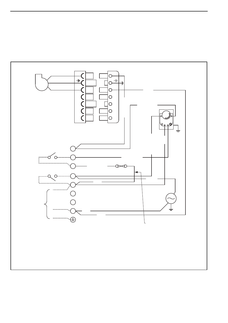
9.3 CCH Wiring Diagram Gas Models 15-30 (floor standing)
Note: Remote fan control
carries full load of fan motor
7 amp inductive
Red
1
2
3
4
N
10 A
Red / White
Red / White
R
ed /
W
hit
e
R
ed /
W
hit
e
MAIN
FAN
MOTOR
MAIN TERMINALS
IN CONTROL PANEL
230 V 50 Hz
1 PH SUPPLY
Red / White
TIME/TEMPERATURE
CONTROLS
FAN CONTROL
Blue
Blue
Blue
L
L
L
1
2
3
Re
d
FAN
LIMIT
FAN / LIMIT STAT
Brown
PACKAGED
BURNER
B4
S3
T2
T1
N
L1
B4
S3
T2
T1
N
L1
GAS BURNER 7 WAY PLUG
1 mm2 Ø Red Tri Rated Flex Cable
NOTE:
Any of the original wire supplied with
the heater must be replaced with
wiring material having a temperature
rating of at least 105°C and 600 V.