System configurations, Figure 10, Cd changer – Niles Audio A4.6Ci User Manual
Page 17: Home theater receiver
17
SYSTEM CONFIGURATIONS
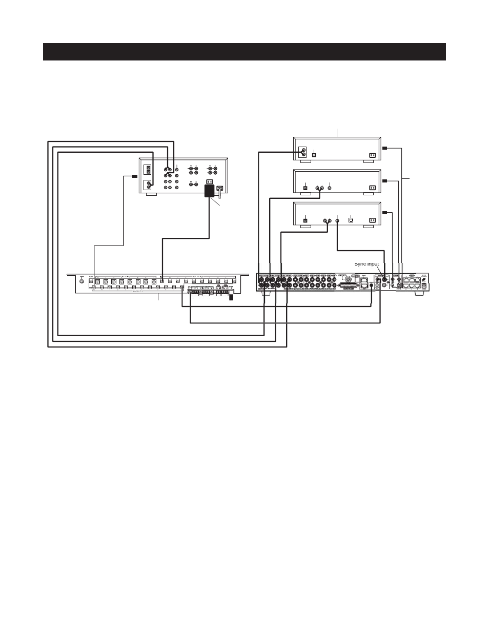
CONFIGURATION 4 – INTEGRATING A HOME THEATER USING AN INTELLICONTROL
A Home Theater system controlled by a Niles IntelliControl
®
can be integrated to share source compo-
nents in a system with the A4.6Ci.
Distributing Audio Signals
Audio signals for the shared source components are connected to both the A4.6Ci and the Home Theater receiver
using the buffered cascade audio outputs (Figure 10).
Shared Source Component Control
The FLASHER output from the IntelliControl (Figure 10) is connected to the IR input of the A4.6Ci. The
IntelliControl, programmed with Niles Remote IR commands, is now able to automate and control the shared
source components. Niles IR commands are taught to the IntelliControl using the A4.6Ci and an attached flash-
er or the R-4 Remote itself (see Programming Overview for more details on page 45).
A 12V Sync signal is provided from the IntelliControl to the Home Theater Sync Input to provide the A4.6Ci
with the On/Off status of the Home Theater. This status enables the A4.6Ci to provide coordinated control of
the source component's power On/Off.
Important Note: When issuing the shared source components’ actual IR commands from the Home Theater
Remote Control, all IR commands are passed through to all shared source component flasher outputs. Identical
brand and model source components cannot be operated individually using these commands. (For more infor-
mation on controlling identical brand and model shared source components, refer to the Operation
Overview on page 28.)
L
R
AUDIO VIDEO
DSS
PHONE
DIGITAL
L
CD CHANGER
R
AUDIO
DIGITAL
L
R
AUDIO VIDEO
DVD
DIGITAL
L
R
AUDIO
CD
VIDEO
FRONT
L
L
R
DIGITAL
1
2
R
CENTER
REAR
L
R
DVD
DSS
Video 1
Video 2
Niles IRC-2P
MicroFlashers
Home Theater Receiver
Source Components
Plugged into
Switched
AC outlet
12V
D.C.
H.T. Sync Input
IntelliControl MSU
Figure 10