Mode 2 bidirectional timing, Mode 2 bidirectional timing -29, Figure 4-15 – National Instruments 6023E User Manual
Page 59
Chapter 4
Signal Connections
© National Instruments Corporation
4-29
Mode 2 Bidirectional Timing
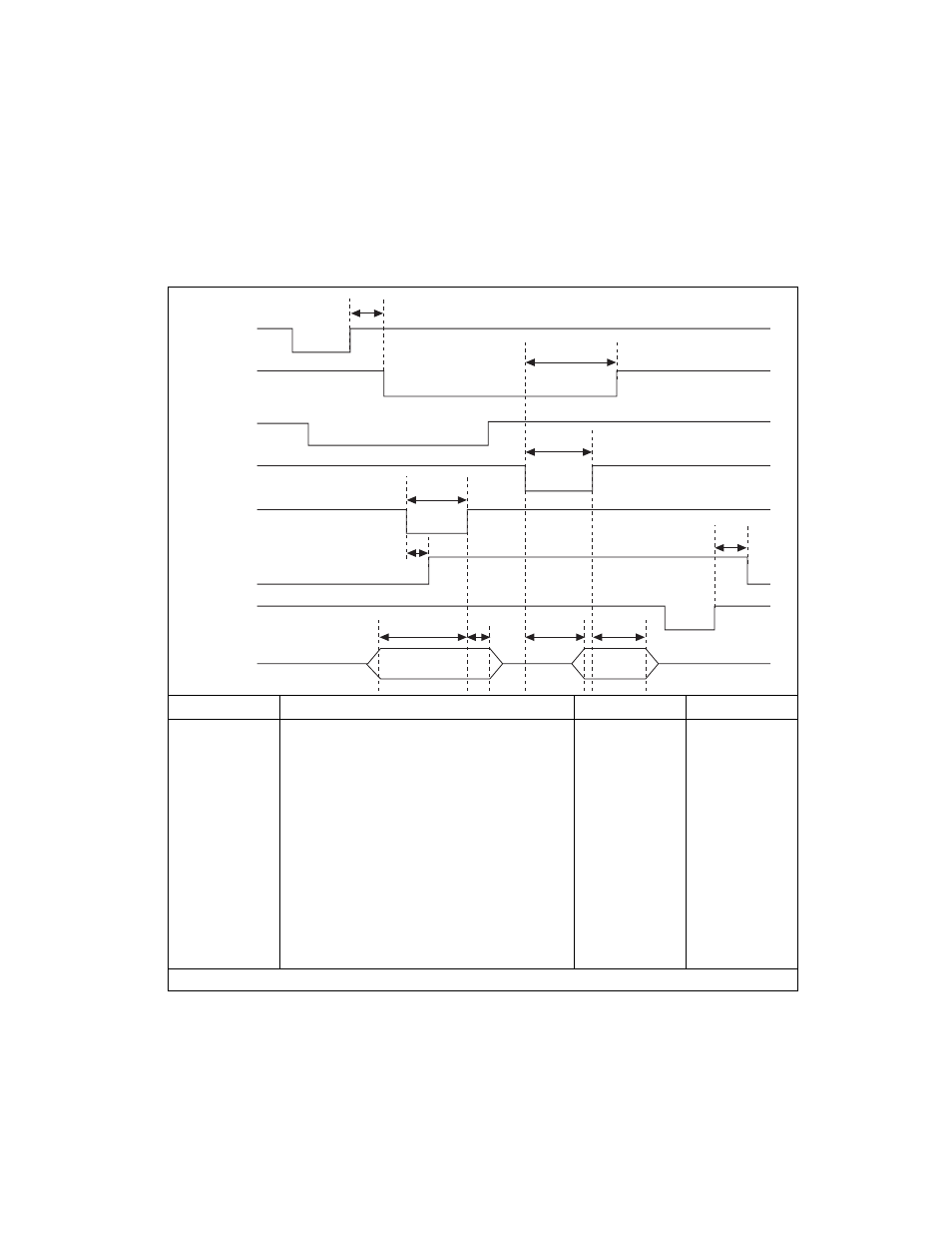
Timing specifications for a bidirectional transfer in mode 2 are shown in
Figure 4-15.
Figure 4-15. Timing Specifications for Mode 2 Bidirectional Transfer
Name
Description
Minimum
Maximum
T1
WR* = 1 to OBF* = 0
—
150
T2
Data before STB* = 1
20
—
T3
STB* Pulse Width
100
—
T4
STB* = 0 to IBF = 1
—
150
T5
Data after STB* = 1
50
—
T6
ACK* = 0 to OBF* = 1
—
150
T7
ACK* Pulse Width
100
—
T8
ACK* = 0 to Output
—
150
T9
ACK* = 1 to Output Float
20
250
T10
RD* = 1 to IBF = 0
—
150
All timing values are in nanoseconds.
T1
T6
T7
T3
T4
T10
T2
T5
T8
T9
WR *
OBF *
INTR
ACK *
STB *
IBF
RD *
DATA