Programmable peripheral interface (ppi), Figure 4-11. digital i/o connections block diagram, Programmable peripheral interface (ppi) -22 – National Instruments 6023E User Manual
Page 52: Figure 4-11, Digital i/o connections block diagram -22, Re 4-11, Ure 4-11
Chapter 4
Signal Connections
4-22
ni.com
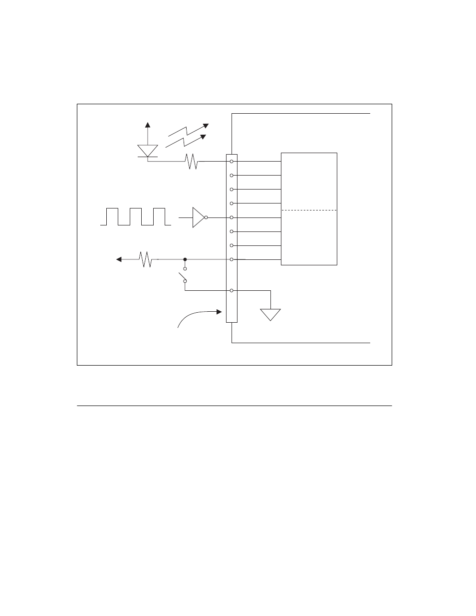
Figure 4-11. Digital I/O Connections Block Diagram
Programmable Peripheral Interface (PPI)
♦ 6025E only
The 6025E device uses an 82C55A PPI to provide an additional 24 lines
of digital I/O that represent three 8-bit ports—PA, PB, and PC. You can
program each port as an input or output port.
In Figure 4-11, port A of one PPI is configured for digital output, and
port B is configured for digital input. Digital input applications include
receiving TTL signals and sensing external device states such as the state
of the switch in Figure 4-11. Digital output applications include sending
GND
DIO Device
Switch
I/O Connector
+5 V
+5 V
LED
Port B
PB<7..4>
Port A
PA<3..0>
TTL Signal