Figure 3-6. pxi rtsi bus signal connection, Table 3-3. pins used by pxi e series device, Figure 3-6 – National Instruments 6023E User Manual
Page 30: Pxi rtsi bus signal connection -11, Table 3-3, Pins used by pxi e series device -11
Chapter 3
Hardware Overview
© National Instruments Corporation
3-11
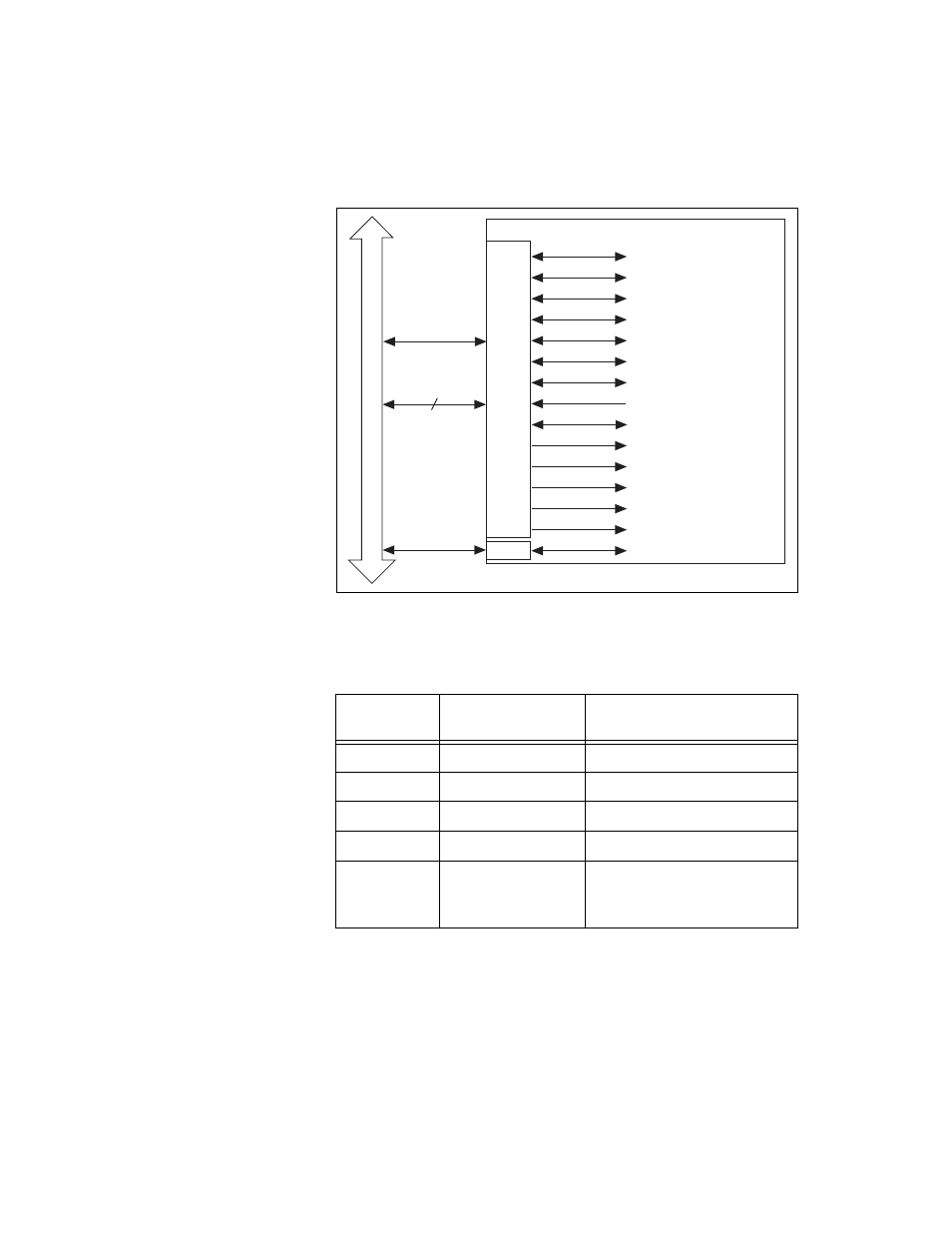
Figure 3-6. PXI RTSI Bus Signal Connection
Table 3-3 lists the name and number of pins used by the PXI-6025E.
Refer to the
section of Chapter 4,
for a description of the signals shown in Figures 3-5 and 3-6.
Table 3-3. Pins Used by PXI E Series Device
PXI E Series
Signal
PXI Pin Name
PXI J2 Pin Number
RTSI<0..5>
PXI Trigger<0..5>
B16, A16, A17, A18, B18, C18
RTSI 6
PXI Star
D17
RTSI Clock
PXI Trigger 7
E16
Reserved
LBL<0..3>
C20, E20, A19, C19
Reserved
LBR<0..12>
A21, C21, D21, E21, A20,
B20, E15, A3, C3, D3, E3,
A2, B2
PXI
Bus
Connector
switch
RTSI
Switch
PXI Trigger (7)
PXI Trigger (0..5)
DAQ-STC
TRIG1
TRIG2
CONVERT*
UPDATE*
WFTRIG
GPCTR0_SOURCE
GPCTR0_GATE
GPCTR0_OUT
STARTSCAN
AIGATE
SISOURCE
UISOURCE
GPCTR1_SOURCE
GPCTR1_GATE
RTSI_OSC (20 MHz)
PXI Star (6)